EFD1000 E5 Dual Electronic Flight Instrument (EFI) Install Manual
DOCUMENT # 900-00041-001
PAGE 123-226
REVISION D
© Copyright 2019 Aspen Avionics Inc.
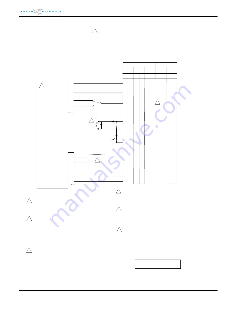
Figure 9-19B: NAVOMATIC 400/400A Autopilot to ACU Interface
Set ACU HSI TYPE = 1
Set ACU DATUM = REVERSED
Configuration Matrix
(see Section 10)
25
23
22
P3
HDG DATUM
HDG-CRS EXT
ACU
GND= NAV, OPEN= HDG
1
3
CRS DATUM
K1
2
2
The relay allows the HDG Bug to be used in heading
mode and the CRS Pointer to be used in NAV/APPR
modes. Optionally the relay may be omitted and ACU
P3-22 wired directly to HDG GYRO Signal IN of the
mode controller (HDG Bug will be used in HDG and
NAV modes). K1 must be rated for 14V or 28V
depending on autopilot operating voltage, P/N M5757/
10. Diodes are 1N4005.
AP ON (14V or 28V)
HDG GYRO Signal IN
400Hz Ref Source (10Vac)
400Hz Ref Common (4.5Vdc)
3
Refer to autopilot manufacturers’ documentation for
autopilot-side integration information (including autopilot
STC compliance data) and for autopilot and flight director
checkout procedures. This drawing, as it pertains to the
non-Aspen equipment, is for reference only.
Existing wire between
controller and computer
amp. Insert diode in line.
Verify 10Vac goes to ACU P3-23 and 4.5Vdc goes to
ACU P3-25 before connecting the ACU. Sometimes
the 10Vac and 4.5Vdc signals are reversed at the
mode controller.
1
EXT-OFFSET
P3
CA-520/B
AP Mode Controller
AP Computer
CA-530A
C-520A/B C-530A
C-420A
J1/P10
P5
B
P1
P1
P1
P2
P3
A
E
M
N
L
P2
35
16
37
18
+ RIGHT
+ LEFT
+UP
+DN
X
B
C
A
X
R
M
N
B
D
A
or
E
M
B
N
A
C
D
a
5
ILS Energize
NAVOMATIC 400/400A
_
_
_
_
_
_
_
_
_
_
_
_
_
_
_
_
_
_
_
_
_
_
_
_
_
_
_
_
_
_
_
_
_
_
_
_
_
_
_
_
_
_
_
_
_
_
_
_
_
_
_
_
_
_
_
_
_
_
_
_
_
_
_
_
10
EXT-COM
_
_
_
_
_
_
_
_
400Hz Ref Common
This interface drawing pertains to a 400 or 400A system with
the following Mode Controller and AP Computer combinations:
C-420A and a CA-520/B
C-520A/B and a CA-520/B
C-520A/B and a CA-530A
C-530A and a CA-530A
3
If the mode controller has a integrated HDG knob then it
must be modified to work with an external DG.
4
5
The R/L output is no different than any previous HSI/
NAV interface and may need to be run through a
Backcourse relay circuit in the Cessna audio control
panel or other existing BC relay box.
4
5 NOTE – The C-420A controller could be internally wired
in several ways. The HDG IN can be pin A or pin E.
Use a ohm meter to check which pin is internally
jumpered to C-420A J3 pin D (either A or E) and use the
opposite pin for the connection to K1 wiper.
6


