EFD1000 E5 Dual Electronic Flight Instrument (EFI) Install Manual
DOCUMENT # 900-00041-001
PAGE 132-226
REVISION D
© Copyright 2019 Aspen Avionics Inc.
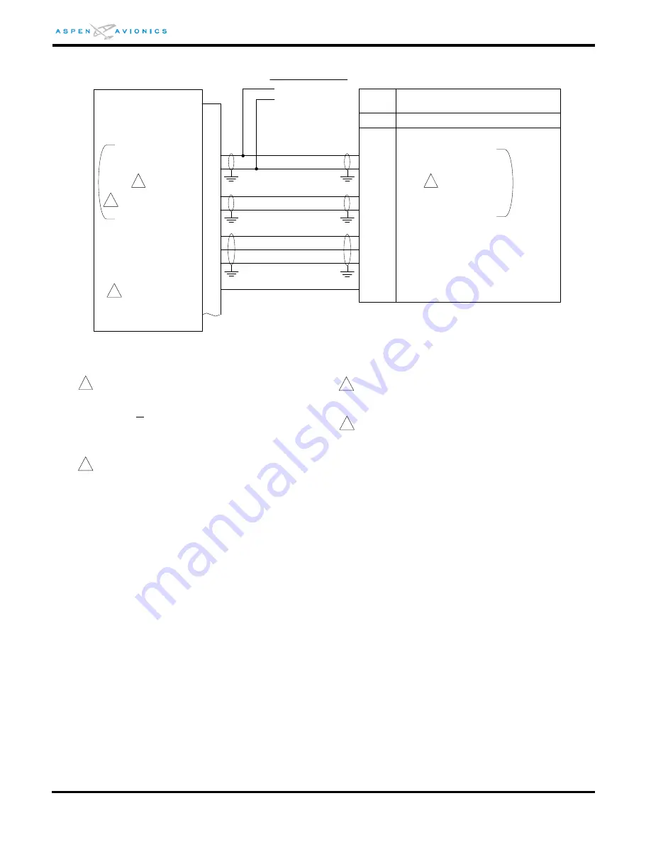
Figure 9-28B: ARINC 407 Synchro Output (ACU2 only)
Pin
Description
Pxxx
ACU2
25
400HZ REF HI (out)
400HZ REF LO (out)
4
26
5
HDG X
HDG Y
ARINC 407 Synchro
Heading “bootstrap”
27
52
P4
HDG Z
/SYN-HDG VALID
60
26V 400HZ REF- H (in)
61
26V 400HZ REF- C (in)
26V 400Hz external ref H
26V 400Hz external ref C
From inverter or
other 26V 400Hz source
26V 400HZ REF- H (in)
26V 400HZ REF- C (in)
26V 400HZ REF- H (in)
26V 400HZ REF- C (in)
SYNCHRO X INPUT
SYNCHRO Y INPUT
SYNCHRO Z INPUT
HEADING VALID LO
2
1
1
1 The ACU2 and the device requiring the synchro heading
input must use the same 400HZ reference. Either wire the
400HZ from the external source in to both the ACU2 and
the device or use ACU2 400HZ output as reference to
device. Note if a external reference is connected to pins
60/61, the ACU2 will disable the internal 400HZ reference
output on pins 25/4.
2
/SYN-HDG VALID is a active Lo output when the heading
system is valid. If the device requires a active Hi input
then use this output to drive a relay to invert the signal.
This output can sink up to 100ma to ground.
3
Refer to manufacturers’ documentation to verify the
integration data and for information regarding checkout
procedures. This drawing, as it pertains to the non-Aspen
equipment, is for reference only.
or
or
4
ACU2 26Vrms@400Hz reference output can support up to
0.06VA. If more than one analog load is required use an
external inverter.
3


