EFD1000 E5 Dual Electronic Flight Instrument (EFI) Install Manual
DOCUMENT # 900-00041-001
PAGE 214-226
REVISION D
© Copyright 2019 Aspen Avionics Inc.
NOTE – The EA100 must be configured using the EA100 Tool, See Section E5.8 in this document.
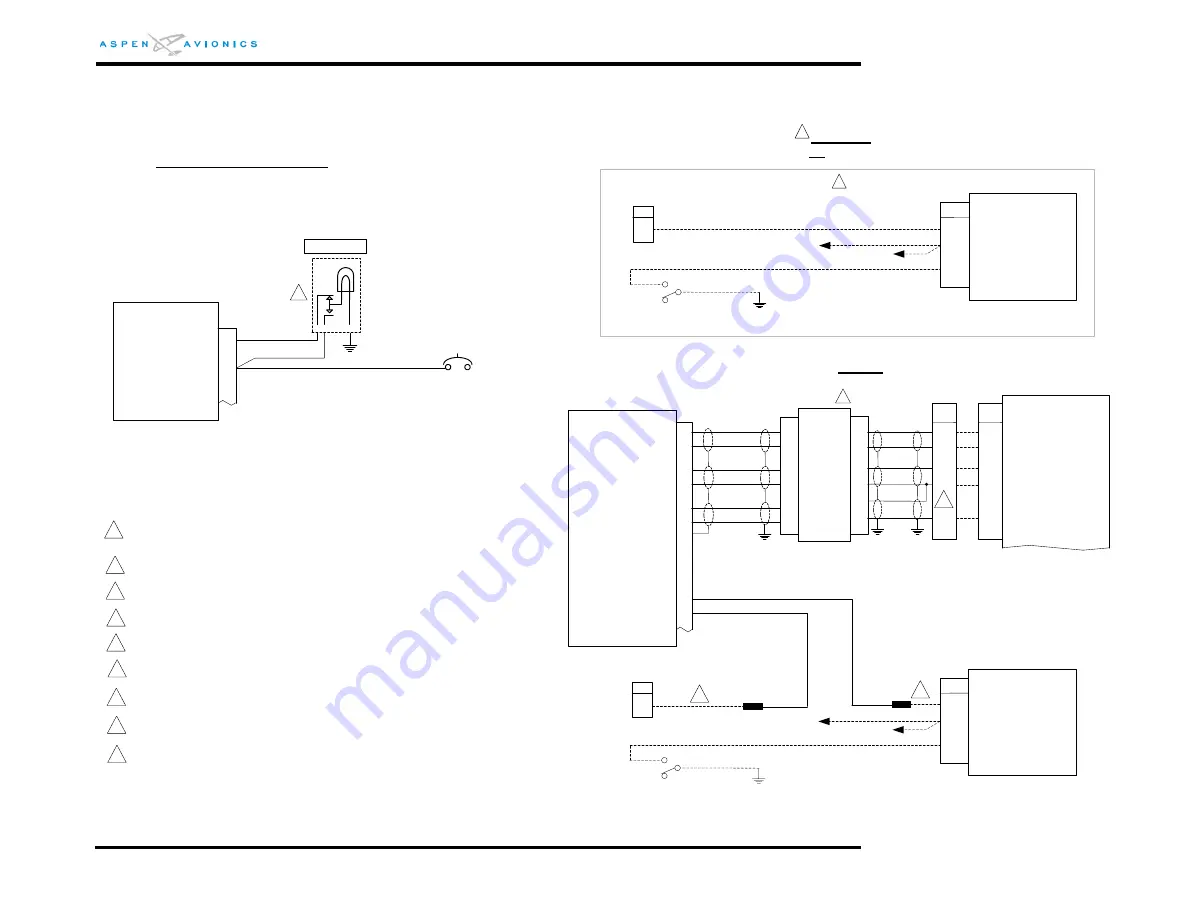
Figure E17: EA100 to Century IV Attitude Source w/DISC
2
A/P AHRS FAIL light must be installed in the pilots primary field of view. Use light/dimmer/test switch
P/N MS25041-4. Wire as shown. Use 14v or 28v bulb as appropriate.
3
4
This note is not used
This note is not used
5
6
This note is not used
7
GENERAL INSTALLATION NOTES
All wires in this section 22AWG unless otherwise specified
All grounds should be as short as possible
Terminate all shields within connector back shell
EA100
41
39
3
16
1
P2
AP EXCITE HI
AP EXCITE LO
AP ROLL HI
A/P INTRLK COMM
A/P INTRLK ENERGIZED
17
2
AP PITCH HI
AP PITCH LO
A
D
C
A/P EXCITATION
PITCH GYRO SIG
B
ROLL GYRO SIG
A/P REFERENCE
The existing autopilot disconnect circuit must be run through an internal relay within the EA100. This
ensures the autopilot cannot be engaged or will disengage if the EA100 attitude is invalid. The
autopilot “sonalert” or disconnect tone must not be interrupted with this relay. Wire as shown.
CD64
Remove wire from CD81-B (1A544 Relay Box) and install new pin/wire or cut wire and splice on
new wire. Run new wire from CD81-B to EA100 P2-41.
3
After
TR2 Transformer Interface box must be field fabricated using the instructions in this Appendix.
E
PITCH/ROLL REF
18
22
23
19
24
CD66
Transformer
Interface Box
(See Figure
E7A for
internal
components
and
connections)
P1
P1
The old wire that was going to CD81-B (from CD82-29) will need to be lengthened and run to
EA100 P2-39 or install new pin/wire in CD82-29 and run new wire to EA100 P2-39.
6
7
8
9
10
11
1
2
3
4
5
2
43
44
A/P AHRS COMM
A/P AHRS INVALID
A/P AHRS FAIL
A/P circuit
breaker
(existing)
P2
2
1
3
MS25041-4
20 AWG
20 AWG
EA100
1
8
8
TR2
Century IV
(1D496 computer)
Before
A/P DISC Switch OR Century Relay Box (partial)
1
18
AP ROLL LO
- - - equals Existing Wires
S3
A/P DISC SW
CD81
B
1
C
A/P GND
1A544(1)
– Relay Box
To CD66 pin 38
A
To A/P Master or C/B
TRIM SWITCH on YOKE
Trim Enable/AP Disc
TYPE 15 Trim
Systems
CD82
29
1C543-1
System Coupler
Existing wire
– no change
S3
A/P DISC SW
CD81
B
C
A/P GND
1A544(1)
– Relay Box
To CD66 pin 38
A
To A/P Master or C/B
TRIM SWITCH on YOKE
Trim Enable/AP Disc
TYPE 15 Trim
Systems
CD82
29
1C543-1
System Coupler
7
14
9
9
The tie point of the transformer low wiring coming from pins 4 & 14 of TR2 should be as close to
the autopilot computer as possible to eliminate any pitch/roll interaction..


