EFD1000 E5 Dual Electronic Flight Instrument (EFI) Install Manual
DOCUMENT # 900-00041-001
PAGE 56-226
REVISION D
© Copyright 2019 Aspen Avionics Inc.
3)
Remove burrs and break sharp edges on the panel (0.005” – 0.015”).
4)
Chemical conversion coat the bare aluminum and primer or paint as required.
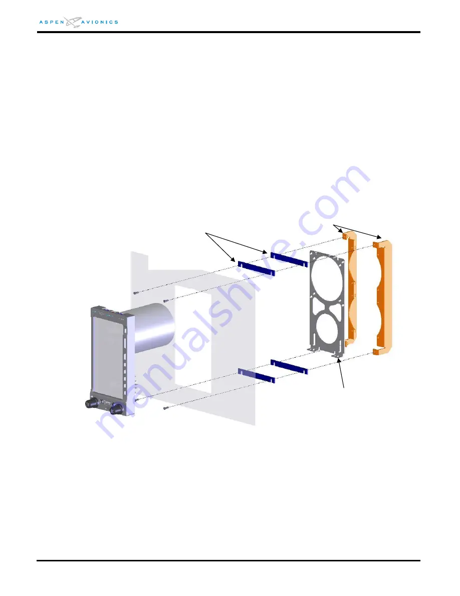
STEP 6 – Install the Recess Mount Brackets and Hardware (Use Figure 6-4 for reference)
1)
Fit the spacers (A) between instrument panel and recess brackets (C) as shown
in Figure 6-4, using four MS24693-S26 6-32 X 3/8 machine screws or pan
head screws may be used if that look is desired. Tighten all four mounting
screws and nuts to 12 in-lbs anchoring the brackets to the panel.
NOTE: Spacers (A) come in a strip of three which can be snapped apart. The thickness of the
instrument panel will determine how many spacers will be required. Instrument panels that are
1/8” thick should require one spacer while 1/16” panels may require up to four spacers to
provide the desired appearance.
2)
Mount EFD Bracket (B) to Recess Brackets (C) using six MS24693-S24 6-32 X ¼
flat head machine screws.
3)
Tighten all six mounting screws and nuts to 12 in-lbs.
Figure 6-4: Single Display Recess Mount Bracket Installation
STEP 7 – Assemble and Attach the EFD Ground Strap
1)
Fabricate one 8” bonding strap from braid with ground lugs at each end.
Spacers (A)
Two spacers are shown
for reference (0 to 4
may be required)
Recess Brackets (C)
EFD Bracket (B)


