EFD1000 E5 Dual Electronic Flight Instrument (EFI) Install Manual
DOCUMENT # 900-00041-001
PAGE 57-226
REVISION D
© Copyright 2019 Aspen Avionics Inc.
2)
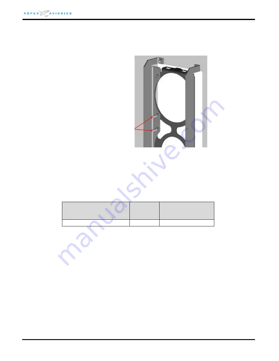
Insert a MS24693-S30 6-32 x ¾” flat head machine screw through either an
unused threaded insert or an existing EFD bracket attachment screw (see
Figure 6-5). Attach one end of the ground strap to this screw using a
MS21044N06.
Figure 6-5: Ground Strap Attachment Points
STEP 8 – Perform the Structural Load Test on the Bracket Installation
The following test is to structurally substantiate the bracket installation. The applied
static test load is determined using 2.9lbs for the EFD mass. See AC 43.13-2B for
additional Structural Data.
Direction of Pull
(push on bracket)
Load
Factor
Static Test Load
(load factor x EFD
weight)
Forward (toward firewall)
9.0g
9.0 x 2.9 = 26 lbs
Table 6-3: Static Load Table
Use a block of wood or piece of aluminum that will cover the EFD bracket. This
ensures an even force is applied to the entire bracket at once. Place mechanical or
digital push/pull gauge against block and assert the static test load defined in the
table above for a minimum of 3 seconds. Ensure instrument panel and brackets show
no signs of permanent deformation.
NOTE: The recessed brackets are TSO’d and meet the sideward, upward, downward, and forward axis
load requirements of the EFD. Therefore only the forward axis is tested above to substantiate
the overall bracket installation.
Location of 6-32 X ¾” screw
for ground strap attachment


