EFD1000 E5 Dual Electronic Flight Instrument (EFI) Install Manual
DOCUMENT # 900-00041-001
PAGE 73-226
REVISION D
© Copyright 2019 Aspen Avionics Inc.
4)
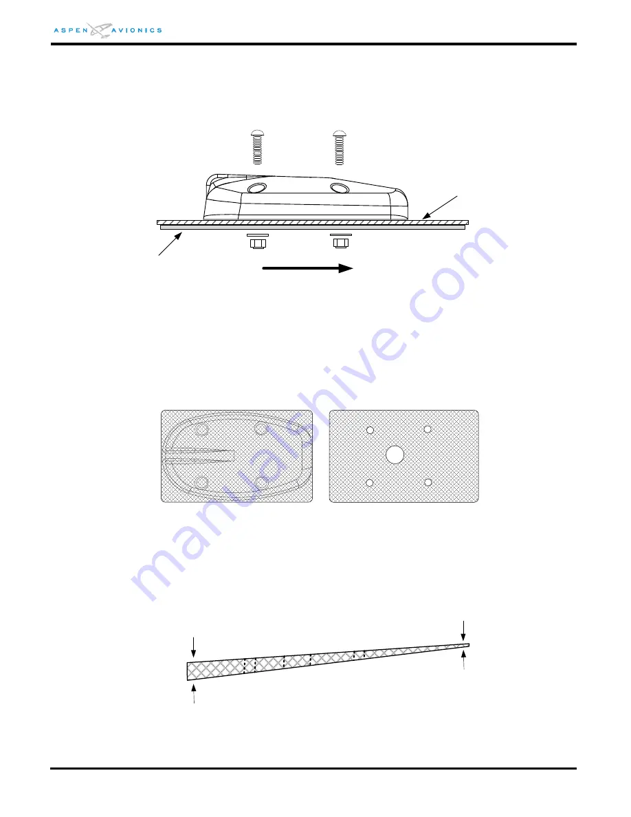
Torque hardware to 12-15 in-lbs. Do not over-torque the hardware as it may cause the
RSM housing to crack.
5)
Attach ring terminal to ground stud on RSM doubler tab.
6)
Apply a bead of non-corrosive sealant around the RSM.
Figure 6-22: RSM Mounting
6.9.11
RSM Shim Fabrication (if necessary)
If the RSM exceeds the mounting limits of Section 6.9.7 a shim will be required.
Fabricate a shim with the dimensions of the RSM baseplate. Optionally the shim can be
made square and slightly larger than the RSM baseplate for ease of construction (see
Figure 6-23).
Figure 6-23: Example Shim Top View
The shim must not exceed the minimum and maximum thickness as shown in Figure
6-24. Use of a thicker shim is acceptable but not approved under this STC. A thicker
shim will require a local approval.
Figure 6-24: Example Shim Side View
Doubler
(installer fabricated)
Aircraft Skin
FWD
No Thinner than 0.040"
No Thicker than 3/8"


