background image

SPNTWB

LECTROSONICS, INC.

18

Using the LCD

The LCD can be used to check current settings or make 

adjustments without using a computer interface.

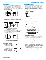
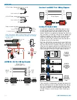
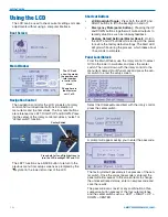
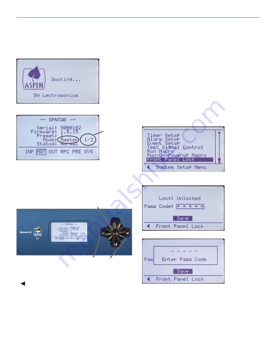
Boot Screen

Main Window

The LCD will 

show the mode, 

the position and 

total number 

of units in the 

stack.

Shown here is 

the Master as 

unit 1 of 2.

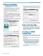
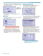
Navigation Control

The navigation control for the LCD consists of a rotary 

control and four directional buttons for selection of 

menu items and to enter values. The four outer buttons 

are referenced as LEFT, RIGHT, UP and DOWN. Press-

ing the center of the rotary control provides a “select” or 

“center switch” function.

Press both Left and Right buttons to 

turn the LCD backlight OFF and ON

Center Switch

The LEFT functions as a BACK button to return to the 

previous menu from setup screens as prompted by the 

 symbol in the lower left corner of the LCD.

Shortcut Buttons

• 

LCD Backlight Toggle:  

Press both the LEFT and 

RIGHT buttons to turn the backlight on and off.

• 

Emergency Mute (panic button):  

Pressing the UP 

and DOWN buttons together will mute all outputs to 

remedy situations such as runaway feedback.

• 

Restore Default Settings (Master Reset):  

Hold in 

the LEFT and UP buttons while turning on the power 

to restore the factory default settings. The Alert LED 

will glow white during the process, which takes about 

75 seconds to complete.

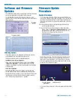
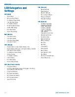
Panel Lock/Unlock

From the Main Window, use the rotary control to select 

SYS

 in the lower row window and press the center 

switch. Then scroll down with the rotary control to the 

menu item named 

Front Panel Lock

 and press the cen-

ter switch to enter the setup screen.

Select the 

Unlocked/Locked

 item with the rotary control, 

press the center switch.

A prompt will appear asking you to enter the passcode.

The factory default passcode is five presses of the cen-

ter switch. Once the correct passcode is entered, the 

panel will allow access to the screen items to change 

the unlocked/locked status, enter a new passcode and 

save the results.
The passcode can consist of any combination of five 

successive button presses of the four outer switches 

and the center switch such as:  LEFT > RIGHT > UP > 

DOWN > CENTER.

Summary of Contents for SPNTWB

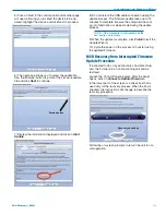
Page 1: ...NTWB Trio Conference Interface Wideband Bridging INSTALLATION and STARTUP GUIDE Software and Hardware Installation and Setup IMPORTANT See page 14 for Minimum Setup Requirements Visit the ASPEN Suppor...

Page 2: ...SPNTWB LECTROSONICS INC 2...

Page 3: ...ed use caution when moving the cart appa ratus combination to avoid injury from tip over 13 Unplug this apparatus during lightning storms or when unused for long periods of time Important Safety Instr...

Page 4: ...rease even with brief signal peaks from the far end and convergence will never be lost with any type of signal or in double talk situations Signals from the far ends of the conference are routed to th...

Page 5: ...agram 10 Crestron and AMX Port Wiring Diagram 10 Cabling Of Stacked Units 10 Software Installation 11 Refer to the Help Files 11 Creating an ASPEN Installer Disk 11 Software and Firmware Updates 12 Fi...

Page 6: ...dure to update the firmware in the processor See the section on Firmware Update Pro cedure for details Status LEDs Comm LED blinks to indicate USB RS 232 and ethernet communication Alert LED blinks to...

Page 7: ...ed differential type Channels 1 through 8 on each board are nominal line level outputs with gain adjustment from 60 to 20 dB Channels 9 through 12 on each board are also line level outputs with switch...

Page 8: ...damage to the front panel s finish when tightening the mounting screws All ASPEN processors have internal switching power supplies that can tolerate voltages ranging from 100 to 240 VAC Use an approve...

Page 9: ...imum usable voltage for the pro grammable outputs is 40 V and they will safely conduct up to 100 mA DC continuous Both LEDs and 5V relay coils can be powered by the 5 V DC pins on the programmable inp...

Page 10: ...connector Male connector Female jack Male jack Cabling Of Stacked Units In a stacked configuration ASPEN processors must be interconnected as shown here Each Slave unit in a stack gathers data and au...

Page 11: ...lation It is best to check all three boxes so the the USB driver Control Panel and Help utility will all be installed Follow the on screen prompts to complete the installa tion On the last screen clic...

Page 12: ...on your local drive The result ing filename will indicate the model number and ver sion followed by the extension update Firmware Update Procedure Update Procedure 1 It is assumed that the USB driver...

Page 13: ...bernation or sleep mode during the update process NOTE If the procedure is interrupted see the next section on recovery 9 When the update is complete click Finish to exit the Update Wizard 10 Cycle th...

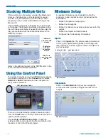
Page 14: ...for several minutes It is good practice to turn all units on simul taneously or turn on Slave units before turning on the Master unit The available processors will appear in a stack in the control pan...

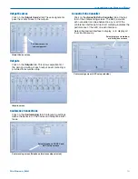
Page 15: ...encing settings define the behavior of the Codec and Telephone inter faces Conferencing screen Telephone Interface setup selected Select Telephone CODEC and AEC setup screens Acoustic Echo Canceller C...

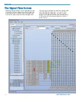
Page 16: ...entire signal chain Double left click and single right click actions open setup and status dialogue boxes The view may be panned or zoomed as needed Hold down the CTRL key and press to zoom in Hold d...

Page 17: ...llation and Startup Guide Rio Rancho NM 17 Unused crosspoint columns can be hidden and unhid den by highlighting a range of Mixes across the top followed by a right click and selection of the desired...

Page 18: ...y Mute panic button Pressing the UP and DOWN buttons together will mute all outputs to remedy situations such as runaway feedback Restore Default Settings Master Reset Hold in the LEFT and UP buttons...

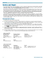
Page 19: ...LED will light up to indicate power ON and a ready status Navigating Individual Settings The following example illustrates the structure of the LCD screens used to set up the processor Select a catego...

Page 20: ...p EQ Filter Setup Output Group Setup RPC Rear Panel Control Prog Input Setup Virt Prog Input Setup slave unit triggers from Prog Input activity on Master unit Prog Output Setup RP Input Gain Setup RP...

Page 21: ...t take effect until the processor power is cycled off and back on again Web Browser Interface A simple interface is provided to communicate directly with the processor through a network using the HTTP...

Page 22: ...turning Units for Repair For timely service please follow the steps below A DO NOT return equipment to the factory for repair without first contacting us by e mail or by phone We need to know the natu...

Page 23: ...scontinuance of service may be required If advance notice isn t practical the telephone company will notify the customer as soon as possible Also you will be advised of your right the file a complaint...

Page 24: ...rosonics Inc will pay for the cost of returning your equipment to you This warranty applies only to items returned to Lectrosonics Inc or an authorized dealer shipping costs prepaid within three years...

Reviews: