EP2C612D16FM / EP2C612D16FM-N
Quick Installation Guide
www.asrockrack.com
Activity / Link LED
Speed LED
Status
Description
Status
Description
Off
No Link
Off
10M/100Mbps
connection or no link
Blinking
Yellow
Data Activity
Green
1Gbps connection
On
Link
8
LAN Port LED Indications
Recommended Memory Configurations
5
7
11
6
1
2
3
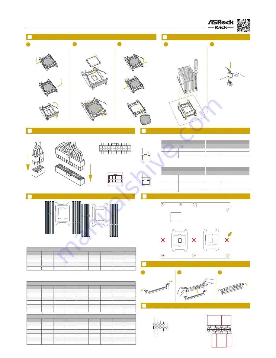
Open the socket levers and the
CPU socket cover.
Install the processor and close
the socket cover.
Close the socket levers. Remove
the CPU protection cap.
Install the CPU Fan and Heatsink
CPU
_FA
N
1
2
Apply the thermal grease. Install the
CPU fan and heatsink and secure
the screws.
Connect the CPU fan to the CPU
FAN connector.
Install the Memory
Install the Power Cables
1
2
3
Unlock a DIMM slot by
pressing the module clips
outward.
Insert the memory module.
Lock the clips.
10
Screw Holes
IPMI LAN Port
1G LAN Port
System Panel
Auxiliary Panel
12
Headers
9
A
B
A
B
A
B
A
B
B
A
Activity / Link LED
Speed LED
Status
Description
Status
Description
Off
No Link
Off
10Mbps connection
Blinking
Data Activity (100Mbps)
Orange
100Mbps connection
On
Link
Green
1Gbps connection
Install the Processor
ACT/LINK LED
SPEED LED
LAN Port
ACT/LINK LED
SPEED LED
LAN Port
GND
RESET#
PWRBTN#
PLED-
PLED+
GND
HDLED-
HDLED+
1
GND
G
N
D
S
M
B
_C
LK
S
M
B
_A
le
rt
C
A
S
E
O
P
E
N
1
S
M
B
_D
A
T
A
+3
V
S
B
LA
N
1_
LI
N
K
LE
D
_P
W
R
LA
N
2_
LI
N
K
LE
D
_P
W
R
+5
V
S
B
G
N
D
G
N
D
LO
C
AT
O
R
LE
D
1+
LO
C
AT
O
R
LE
D
1-
LO
C
AT
O
R
B
T
N
#
S
ys
te
m
F
au
lt
LE
D
-
A
B
C
D
S
ys
te
m
F
au
lt
LE
D
+
E
1
3V
3V
GN
D
GN
D
5V
5V
GN
D
PWROK_PS
5VSB
12
V
12
V
3V
3V
-12V
GN
D
PSON#
GN
D
GN
D
GN
D
5V
5V
5V
GN
D
N/
A
12
24
13
4
8
1
5
+12V2
GND
1 CPU Configuration
CPU1
A1
A2
B1
B2
C1
C2
D1
D2
1 DIMM
#
2 DIMMS
#
#
4 DIMMS
#
#
#
#
8 DIMMS
#
#
#
#
#
#
#
#
2 CPU Configuration
CPU1
A1
A2
B1
B2
C1
C2
D1
D2
1 DIMM
#
2 DIMMS
#
#
4 DIMMS
#
#
#
#
8 DIMMS
#
#
#
#
12 DIMMS
#
#
#
#
#
#
#
#
16 DIMMS
#
#
#
#
#
#
#
#
CPU2
E1
E2
F1
F2
G1
G2
H1
H2
1 DIMM
2 DIMMS
4 DIMMS
8 DIMMS
#
#
#
#
12 DIMMS
#
#
#
#
16 DIMMS
#
#
#
#
#
#
#
#
CPU1
CPU2
DDR4-_A1
DDR4_A
2
DDR4_B
1
DDR4_B
2
DDR4_D2
DDR4_D1
DDR4_C2
DDR4_C1
DDR4_E
1
DDR4_E
2
DDR4_F
1
DDR4_F
2
DDR4_H2
DDR4_H1
DDR4_G
2
DDR4_G
1
We recommend using the CPU Installation tool to avoid CPU pin-bent problem.
Rear I/O
Intel
C612
Remove the standoffs
from the chassis
All manuals and user guides at all-guides.com