


2 3
2 3
2 3
2 3
2 3
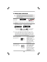
2.7 HDMI_SPDIF Header Connection Guide
2.7 HDMI_SPDIF Header Connection Guide
2.7 HDMI_SPDIF Header Connection Guide
2.7 HDMI_SPDIF Header Connection Guide
2.7 HDMI_SPDIF Header Connection Guide
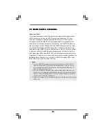
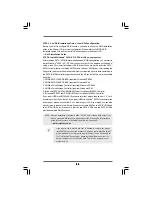
HDMI (High-Definition Multi-media Interface) is an all-digital audio/video specification,
which provides an interface between any compatible digital audio/video source,
such as a set-top box, DVD player, A/V receiver and a compatible digital audio or
video monitor, such as a digital television (DTV). A complete HDMI system requires a
HDMI VGA card and a HDMI ready motherboard with a HDMI_SPDIF header. This
motherboard is equipped with a HDMI_SPDIF header, which provides SPDIF audio
output to HDMI VGA card, allows the system to connect HDMI Digital TV/projector/
LCD devices. To use HDMI function on this motherboard, please carefully follow the
below steps.
•
Make sure to correctly connect the HDMI_SPDIF cable to the motherboard and the
HDMI VGA card according to the same pin definition. For the pin definition of
HDMI_SPDIF header and HDMI_SPDIF cable connectors, please refer to page 21.
For the pin definition of HDMI_SPDIF connectors on HDMI VGA card, please refer to
the user manual of HDMI VGA card vendor. Incorrect connection may cause
permanent damage to this motherboard and the HDMI VGA card.
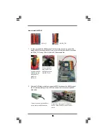
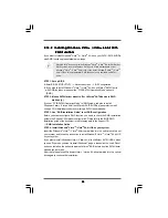
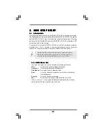
white end
(2-pin) (B)
white end
(3-pin) (C)
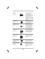
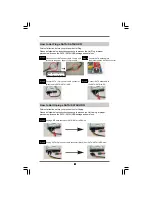
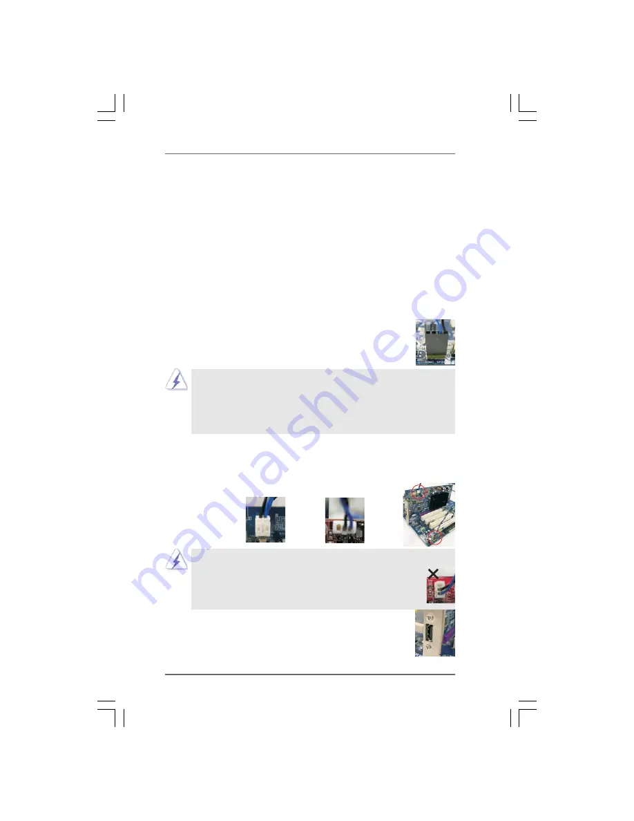
Please do not connect the white end of HDMI_SPDIF cable to the wrong connector
of HDMI VGA card or other VGA card. Otherwise, the motherboard and the
VGA card may be damaged. For example, this picture shows the wrong
example of connecting HDMI_SPDIF cable to the fan connector of PCI
Express VGA card. Please refer to the VGA card user manual for
connector usage in advance.
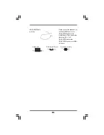
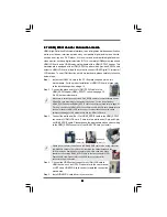
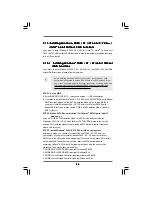
Step 4.
Connect the HDMI output connector on HDMI VGA card to
HDMI device, such as HDTV. Please refer to the user manual
of HDTV and HDMI VGA card vendor for detailed connection
procedures.
Step 5.
Install HDMI VGA card driver to your system.
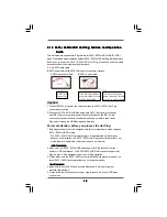
Step 3.
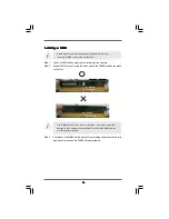
Connect the white end (B or C) of HDMI_SPDIF cable to the HDMI_SPDIF
connector of HDMI VGA card. (There are two white ends (2-pin and 3-pin)
on HDMI_SPDIF cable. Please choose the appropriate white end according
to the HDMI_SPDIF connector of the HDMI VGA card you install.
Step 1. Install the HDMI VGA card to the PCI Express Graphics slot on this
motherboard. For the proper installation of HDMI VGA card, please refer
to the installation guide on page 16.
Step 2.
Connect the black end (A) of HDMI_SPDIF cable to the
HDMI_SPDIF header (HDMI_SPDIF1, yellow, see page 10,
No. 29) on the motherboard.


