


1 3
1 3
1 3
1 3
1 3
ASRock
ALiveDual-eSATA2
Motherboard
EnglishEnglishEnglishEnglishEnglish
2 . 4
2 . 4
2 . 4
2 . 4
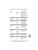
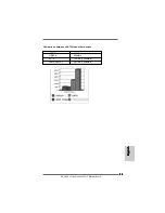
2 . 4 Expansion Slots (PCI Slots, PCI Express slot and AGP
Expansion Slots (PCI Slots, PCI Express slot and AGP
Expansion Slots (PCI Slots, PCI Express slot and AGP
Expansion Slots (PCI Slots, PCI Express slot and AGP
Expansion Slots (PCI Slots, PCI Express slot and AGP
Slot)
Slot)
Slot)
Slot)
Slot)
There are 3 PCI slots, 1 PCI Express slot and 1 AGP slot on
ALiveDual-eSATA2
motherboard.
PCI Slots:
PCI slots are used to install expansion cards that have the 32-bit PCI
interface.
PCIE Slot:
PCIE1 (PCIE x16 slot) is used for PCI Express cards with x16 lane
width graphics cards.
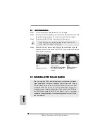
AGP Slot:
The AGP slot is used to install a graphics card. The ASRock AGP slot has
a special design of clasp that can securely fasten the inserted graphics
card.
1. Please do NOT use a 3.3V AGP card on the AGP slot of this
motherboard! It may cause permanent damage! For the voltage
information of your AGP card, please check with the AGP card
vendors.
2. If you plan to install Windows
®
Vista
TM
32-bit / Vista
TM
64-bit OS on
this motherboard, please read the instructions and limitation on
page 169 and 170 carefully. For Windows
®
2000 / XP / XP 64-bit
OS, there is no such limitation.
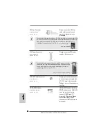
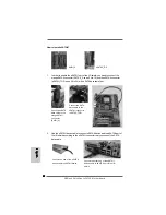
Installing an expansion card
Installing an expansion card
Installing an expansion card
Installing an expansion card
Installing an expansion card
Step 1.
Before installing the expansion card, please make sure that the power
supply is switched off or the power cord is unplugged. Please read the
documentation of the expansion card and make necessary hardware
settings for the card before you start the installation.
Step 2.
Remove the system unit cover (if your motherboard is already installed in a
chassis).
Step 3.
Remove the bracket facing the slot that you intend to use. Keep the screws
for later use.
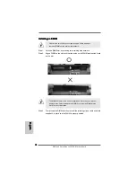
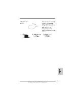
Step 4.
Align the card connector with the slot and press firmly until the card is
completely seated on the slot.
Step 5.
Fasten the card to the chassis with screws.
Step 6.
Replace the system cover.
Summary of Contents for ALIVEDUAL-ESATA2
Page 143: ...143 143 143 143 143 ASRock ALiveDual eSATA2 Motherboard ...
Page 144: ...144 144 144 144 144 ASRock ALiveDual eSATA2 Motherboard ...
Page 145: ...145 145 145 145 145 ASRock ALiveDual eSATA2 Motherboard ...
Page 146: ...146 146 146 146 146 ASRock ALiveDual eSATA2 Motherboard ...
Page 147: ...147 147 147 147 147 ASRock ALiveDual eSATA2 Motherboard ...
Page 148: ...148 148 148 148 148 ASRock ALiveDual eSATA2 Motherboard ...
Page 149: ...149 149 149 149 149 ASRock ALiveDual eSATA2 Motherboard ...
Page 150: ...150 150 150 150 150 ASRock ALiveDual eSATA2 Motherboard DDRII_1 DDRII_2 DDRII_3 DDRII_4 1 2 3 ...
Page 151: ...151 151 151 151 151 ASRock ALiveDual eSATA2 Motherboard ...
Page 152: ...152 152 152 152 152 ASRock ALiveDual eSATA2 Motherboard ...
Page 153: ...153 153 153 153 153 ASRock ALiveDual eSATA2 Motherboard ...
Page 154: ...154 154 154 154 154 ASRock ALiveDual eSATA2 Motherboard SATA1 SATA2 ...
Page 155: ...156 156 156 156 156 ASRock ALiveDual eSATA2 Motherboard CD1 ...
Page 156: ...157 157 157 157 157 ASRock ALiveDual eSATA2 Motherboard 1 2 3 4 12 1 24 13 12 1 24 13 ...
Page 157: ...158 158 158 158 158 ASRock ALiveDual eSATA2 Motherboard C B A ...
Page 158: ...159 159 159 159 159 ASRock ALiveDual eSATA2 Motherboard ...
Page 159: ...160 160 160 160 160 ASRock ALiveDual eSATA2 Motherboard ...
Page 160: ...161 161 161 161 161 ASRock ALiveDual eSATA2 Motherboard ...
Page 161: ...162 162 162 162 162 ASRock ALiveDual eSATA2 Motherboard ...
Page 162: ...163 163 163 163 163 ASRock ALiveDual eSATA2 Motherboard ...
Page 163: ...164 164 164 164 164 ASRock ALiveDual eSATA2 Motherboard ...
Page 164: ...165 165 165 165 165 ASRock ALiveDual eSATA2 Motherboard ...
Page 165: ...165 165 165 165 165 ASRock ALiveDual eSATA2 Motherboard ...
Page 166: ...167 167 167 167 167 ASRock ALiveDual eSATA2 Motherboard ...
Page 167: ...168 168 168 168 168 ASRock ALiveDual eSATA2 Motherboard ...


