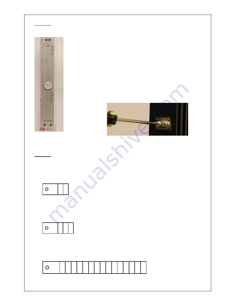
STEP 1 DOOR
PREPARATION
(Fig. 1)
•
Select the stick-on template to match the application.
•
Mark the backset and horizontal centerlines.
•
Apply
clear
template over the centerline marks.
(Fig. 1)
•
Center-punch four (4) referenced mounting holes and
remove template.
•
Drill holes at center-punch locations using a ¼” drill bit.
•
Install Rivnuts. Refer to instructions supplied in R
kit.
ivnut
•
Install mounting bracket (Item 1) with two (2) each
of #10-32 x 5/8” (Item 2) pan head screws.
(Fig. 2)
(Fig. 2)
STEP 2 SPINDLE PREPARATION (For 1-3/4” doors)
For MS1850 Deadbolts, 4500/4900 Deadlatches, & 8000 Series Mortise Exit
Devices, snap-off spindle at third notch as shown in Fig. 3. For 2” thick
door add one notch.
Fig. 3
For 8600 Concealed Vertical Rod Exit Devices snap-off spindle at fourth
notch as shown in Fig.4. For 2” thick doors add two notches.
Fig. 4
For 8000 Series Surface Vertical Rod & Rim Exit Devices, snap-off spindle
at sixteenth notch as shown in Fig. 5. For 2” thick doors add two notches.
Fig. 5
7
80
‐
0180
‐
327
Rev.
A


