®
ASSA ABLOY
ElectroLynx® is a registered trademark of ASSA ABLOY Inc.
Copyright © 2014 Corbin Russwin, Inc. All rights reserved.
Reproduction in whole or in part without the express written
permission of Corbin Russwin, Inc. is prohibited.
14
A
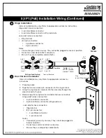
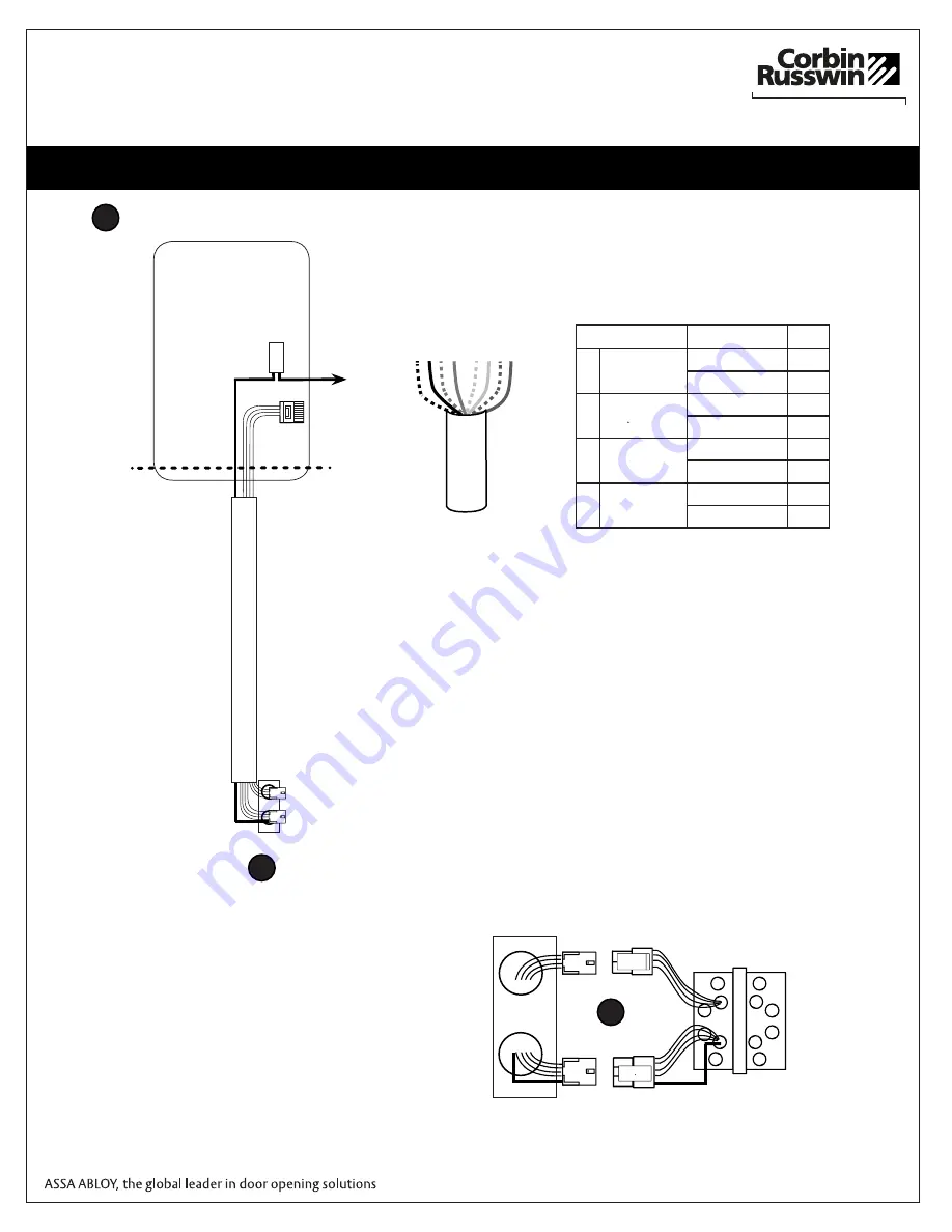
Frame Harness Installation
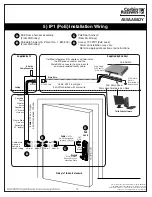
Components and wire harness supplied by McKinney: Suggested installation.
RJ45-M
Molex-M
Cable
: CA
T
5e or higher
24
A
WG shielded, 100ohm
B-Splice
Crimp Connector
Ceiling
Supplied by CI
Each of the hinge-side harness connectors should end up threaded
through a different access hole and matched to the same size pin con-
nector from the door harness:
•
4-pin male Molex connector.
•
6-pin male Molex connector with ground wire.
Notes:
•
Connectors only go on one way. They cannot be plugged to
incorrect position.
•
Do not force and do not offset connectors.
•
Be sure they are completely seated (flush).
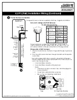
Cut end / ceiling-side PoE harness:
TIA-568-B Standard Wiring
1
2
3 4
5 6
7 8
Pair Number
Wire
PIN
1
White/Blue
White/Blue
5
Blue
4
2
White/Orange
White/Orange
1
Orange
2
3
White/Green
White/Green
3
Green
6
4
White/Brown
White/Brown
7
Brown
8
Do not confuse pair numbers with pin numbers. A pair number is
used for reference only (eg: 10BaseT Ethernet uses pairs 2 & 3). The
pin numbers indicate actual physical locations on the plug and jack.
1. Feed cut end of harness into hole on hinge-side through single access
hole.
2. Push one of the connectors back through hole and feed into separate
access hole.
Hinge side of PoE harness:
B
6-pin F
4-pin M
6-pin M
4-pin F
B
Drain Wire
Frame
PoE Hinge (Patent Pending)
Frame-Side
Harness
Assembly
(15' length)
24AWG
Stranded
Drain
Wire for
Earth
Ground in
15' Frame
Harness
Cable drain wire
concealed in
shrink tubing
5) IP1 (PoE) Installation Wiring (Continued)


