2
FE6600 and BL6600 Series
Installation Instructions
Multi-Point Lock
FM470 03/20
For installation assistance contact Corbin Russwin
1-800-543-3658 • techsupport.corbinrusswin@assaabloy.com
Copyright © 2017, 2019, 2020 ASSA ABLOY Access and Egress Hardware Group, Inc. All rights reserved. Reproduction in
whole or in part without the express written permission of ASSA ABLOY Access and Egress Hardware Group, Inc. is prohibited.
1
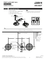
M19S/M19V Occupancy Indicator
Figure 2
Inside of door
Centerline
of lockbody
2-1/2"
Template layout
on door edge.
Outside of door
Fold here according to door hand and bevel
Low side of door
Inside RHRB
Outside LH
No bevel door
High side of door
Inside RH
Outside LHRB
TO
P
Figure 3
2-3/4"
1-3/8"
9/16"
1/2" diameter hole
Lever or
knob
For metal doors:
drill two (2) pilot
holes
0.106 (#36 drill)
and tap
(#6-32 Unc)
9/16"
Cylinder
2-1/2"
Centerline of lockbody


