3
DL2200 and DL3200 Series
Installation Instructions
Cylindrical Deadbolts
FM331 10/19
For installation assistance contact Corbin Russwin
1-800-543-3658 • techsupport.corbinrusswin@assaabloy.com
Copyright © 2012, 2019, ASSA ABLOY Access and Egress Hardware Group, Inc. All rights reserved. Reproduction in whole
or in part without the express written permission of ASSA ABLOY Access and Egress Hardware Group, Inc. is prohibited.
1
Wood Door Preparation
a
Mark Door
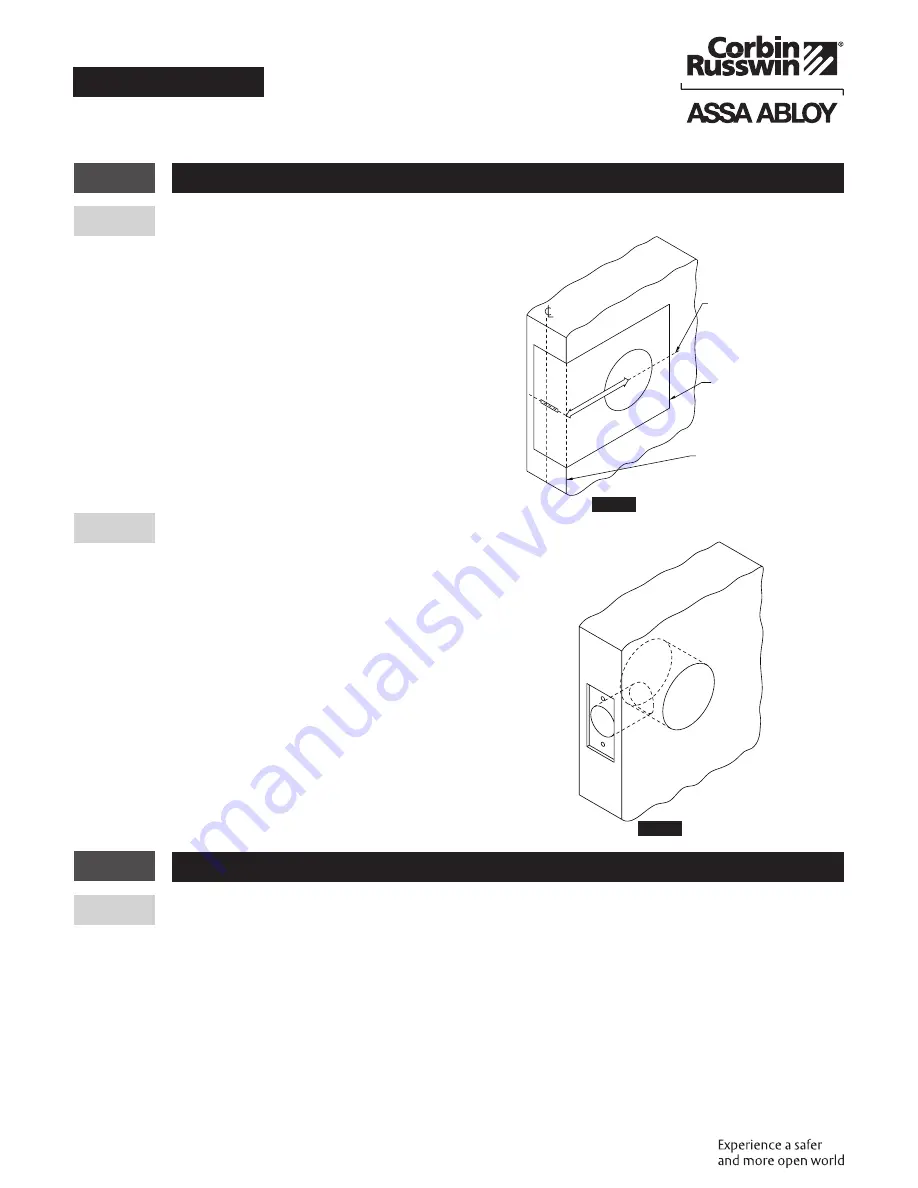
a. Using a square, draw a horizontal line on the edge and
inside surface of the door at the desired height
above floor. 46" (117 m) high is
recommended.
b. Using the enclosed installation template, mark
location of cross bore at proper backset. Mark edge
of door for edge bore at proper centerline location.
b
Mortise and Drill Door
a. Drill holes as directed on installation template. Drill 2-1/8"
(54 mm) dia. cross bore first, (drill from both sides of door to
avoid splintering the wood). Drill 1" (25 mm) dia. edge bore
break through wall of 2-1/8" (54 mm) dia. cross bore.
b. Insert deadbolt unit into hole in edge of door. Using the
deadbolt front as a template, mark outline and location of
two deadbolt screws. Remove deadbolt.
c. Drill pilot holes for two attaching screws, and then mortise
door edge 5/32" (4 mm) deep for deadbolt front. (Figure 2)
2
Frame Preparation
a
Mark Frame
a. Mark center location for strike on door frame at exactly the same height of the deadbolt’s center on
the door.
b. To determine location of vertical centerline of strike, take half of door thickness (measured from
doorstop or silencer). Place strike on door frame and center it on marks. Using the strike as template,
mark the outline and locations of screw holes.
Figure 1
Door Edge
Horizontal
centerline of lock
Installation Template
Figure 2
Typical
finished
door
preparation


