4
DL2200 and DL3200 Series
Installation Instructions
Cylindrical Deadbolts
FM331 10/19
Copyright © 2012, 2019, ASSA ABLOY Access and Egress Hardware Group, Inc. All rights reserved. Reproduction in whole
or in part without the express written permission of ASSA ABLOY Access and Egress Hardware Group, Inc. is prohibited.
For installation assistance contact Corbin Russwin
1-800-543-3658 • techsupport.corbinrusswin@assaabloy.com
b
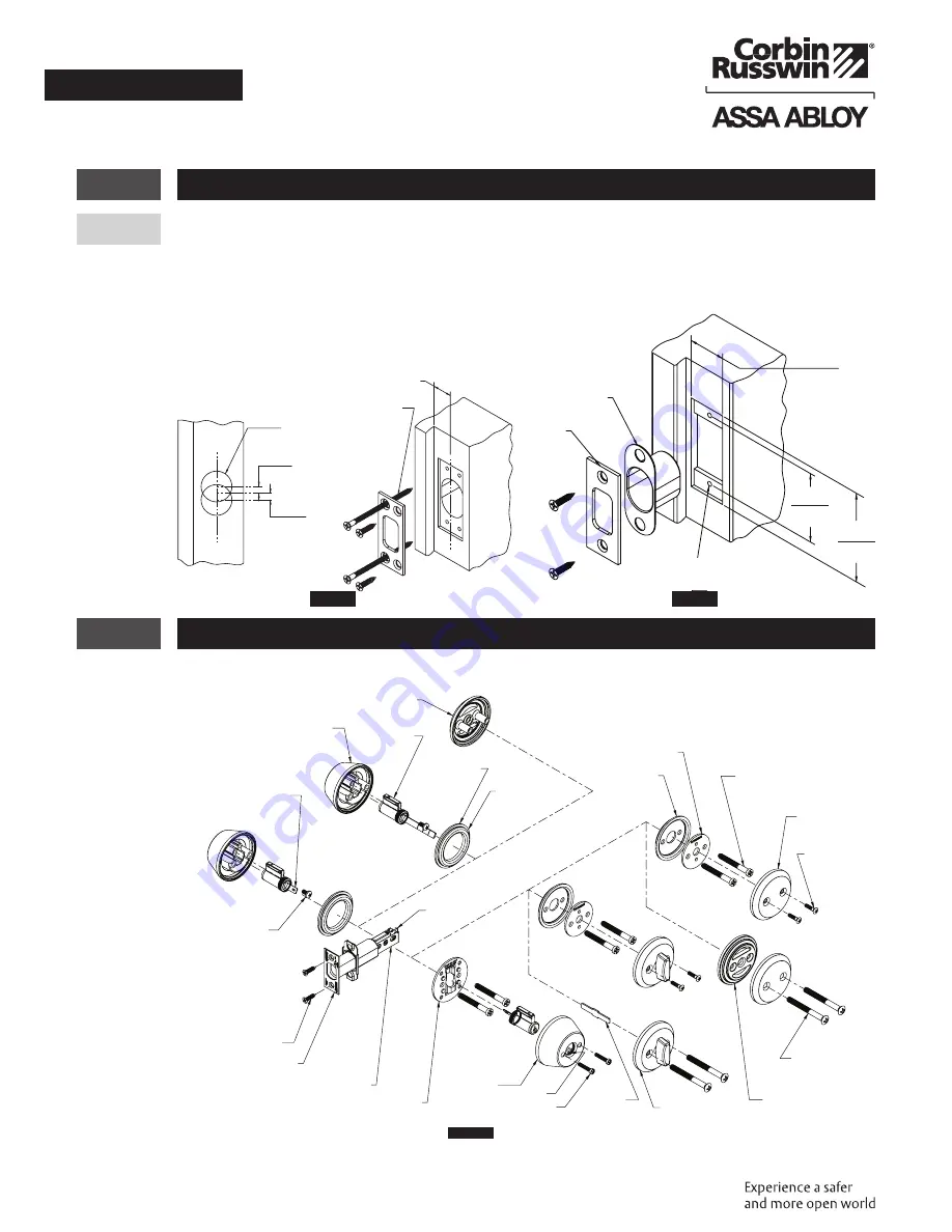
Mortise and Drill Frame
a. Drill two 1" (25 mm) dia. holes 7/32" (5.5 mm) above and below height line to a depth of 1-1/8" (29).
Drill 1/8" (3 mm) dia. pilot holes for 3/4" (19) long screws and 5/32" (4 mm) dia. pilot holes for
3" (76 mm) long screws. (Figure 3)
b. Mortise for strike and strike box.
3
DL2200 and DL3200 Deadbolt Installation
For IC Core Installation, skip to Section 4 .
Figure 5
Blank Plate
Cylinder
Tab
Tab
Cylinder Screw
Deadbolt Screw
Deadbolt Front
Deadbolt Assembly
Mounting Plate
(Double Cylinder)
Inside
Cylinder
Housing
Assembly
#8-32
Screw
#8-32
Screw
Blank Rose
Tailpiece
for 60
Function
Thumbturn
Assembly
Rose
Reinforcement
(DL2200 Series)
Mounting Screw
(DL2200 Series)
Mounting Screw
(DL3200 Series)
Mounting Plate
(DL3200
Series)
Support Plate
(DL3200 Series)
Outside Cylinder
Housing
Assembly
Cylinder
Tailpiece
Housing
Collar
Flip Over
For 1-1/2"
Hole
Ø
Figure 3
1/2 Door
thickness
Long screws
next to door
stop
1.0
25
7/32
(5.5)
7/32
(5.5)
Figure 4
1-1/8
2-1/8
#8-32 THD.
(2 PL)
Strike
box
Strike
2-3/4
(29)
(54)
(70)


