ED5000N (S)(A) Series Exit Device
11
Copyright © 2018 Corbin Russwin, Inc. All rights reserved.
Reproduction in whole or in part without the express written
permission of Corbin Russwin, Inc. is prohibited.
7) Installation Instructions (Continued)
5.
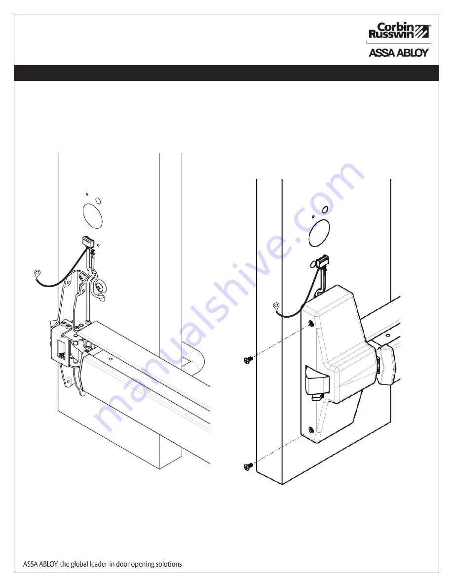
Install Head Cover:
a. Lay wire harnesses (trim harness and device harness) across ¾” hole (Fig. 5a).
b. Tuck wires into hole when installing cover so that wires are not pinched between head cover and door.
c. Attach head cover using (2) #8-32 flat head screws (Fig. 5b).
Use 3/4” hole to
tuck trim and
device wire
harness under
head cover,
Fig. 5a
Fig. 5b


