10
ED5860 (B) Series
Installation Instructions
Exit Device
FM544 02/20
For installation assistance contact Corbin Russwin
1-800-543-3658 • techsupport.corbinrusswin@assaabloy.com
Copyright © 1998, 2020 ASSA ABLOY Access and Egress Hardware Group, Inc. All rights reserved. Reproduction in whole
or in part without the express written permission of ASSA ABLOY Access and Egress Hardware Group, Inc. is prohibited.
b
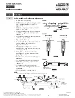
Install Rods
1. Slide rod assemblies into door. (Figure 14-A)
2. Attach top latch with six (6) #10-24 X 1/2
"
PFHMS. (Figure 14-B)
3. Install bottom bolt case with six (6) #10-24 X
1/2
"
PFHMS. (Figure 14-C)
4. Thread set screw into yoke pins (Insert with
hex socket end inside pin).
5. Thread #8-32 x 2
"
PHPMS screws into slotted
end of yoke pins, until seated to hex head set
screw. See Detail 1 - Figure 13.
6. Install two (2) yoke pin assemblies into arm
and bracket assemblies. (Figure 14-E)
Detail 1
Figure 13
1/4
"
(6.4)
Yoke Pin
E-ring Groove
Set Screw
#8-32 PHPMS
Temporary Screws
Figure 14
A
E
B
C
c
Install Device
1. Mount trim when required. (Follow
instructions packed with trim.)
2. Seat device in place. (Figure 15-B)
3. Connect device to arm and bracket assemblies
using temporary screws to position yoke pins
in latch head.
4. Install e-ring into yoke pin grooves.
5. Fasten device latch head using two (2) 1/4-
20 PRHMS or 3/8
"
(10) dia. SNB. (Figure 16)
Remove temporary screws.
Note:
Be certain to retighten yoke pins after removal
of temporary screws.
6. Center end of device on horizontal reference
line of door.
7. Using end clamp as a template, locate end
clamp mounting holes.
8. Prepare end clamp holes and mount end
clamp using two (2) 1/4-20 PRHMS or
3/8
"
(10) SNB. (Figure 15-F)
CL
Figure 15
B
F
C
Detail 1
Device
End
Clamp
1/2
(13)
1-1/4
(32)
Horizontal Ref.
Centerline
Device Screws
(Bolt to door reinforcement,
sex nuts, or trim studs)
Figure 16
E-Ring
Yoke Pin


