4
ED7800 Series
Installation Instructions
Concealed Vertical Rod Exit Devices
FM466 04/20
Copyright © 2018, 2020, ASSA ABLOY Access and Egress Hardware Group, Inc. All rights reserved. Reproduction in whole or in
part without the express written permission of ASSA ABLOY Access and Egress Hardware Group, Inc. is prohibited.
For installation assistance contact Corbin Russwin
1-800-543-3658 • techsupport.corbinrusswin@assaabloy.com
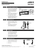
2 Pre-Installation
Important
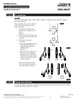
4061, 4062, 4063, 4068, CH641, CH642, CH643, CH648 “U” indicates UL Listed and “MR” indicates
Master Ring Cylinder.
Flush
LHRB
RHRB
Flush
Cover A
Active
Case
Plate
Inactive
Case
Cover B
Active
Case and
Cover B
Inactive
Case and
Cover A
Lift
Figure 3
3
Prepare Door and Frame
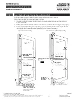
If not already fully prepared, follow template furnished and drawings shown for exposed screw or hidden
(bracket) mounting. See Figure 6 on page 5.
Figure 4
Figure 5
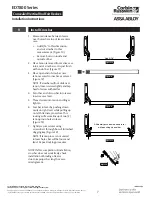
Before installing, check position of parts
for hand of door and reverse hand of
fixture if necessary.
1. To change to opposite hand,
hammer pin to opposite side of
flange.
(Figure 3)
2. Remove case covers by removing
top and bottom screw at back of
each case.
3. Switch case covers and
reassemble.
a. Place cover from present active
case (A) on inactive case,
engaging lifting finger with
bottom of slide.
(Figure 4)
b. Place cover from inactive case
(B) on active case, engaging
lifting finger with bottom of
slide. Be sure that nylon button
on back of cover fits into hole
in plate. (Figure 5)
NOTE: Be sure that plate with
hole in it is positioned in active
case with rounded end down.


