5
ED7800 Series
Installation Instructions
Concealed Vertical Rod Exit Devices
FM466 04/20
Copyright © 2018, 2020, ASSA ABLOY Access and Egress Hardware Group, Inc. All rights reserved. Reproduction in whole or
in part without the express written permission of ASSA ABLOY Access and Egress Hardware Group, Inc. is prohibited.
For installation assistance contact Corbin Russwin
1-800-543-3658 • techsupport.corbinrusswin@assaabloy.com
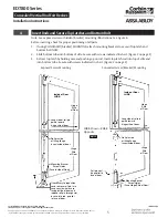
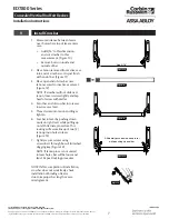
Note: See exposed screw or hidden (bracket) mounting illlustrations. See Figure 6.
Before inserting, check for proper positioning of all parts.
1.
If using CONCEALED (bracket) MOUNTING, attach mounting brackets to cases of top latch and
bottom bolt NOW.
2.
Slide bottom tube into bottom of stile. Secure with screws indicated in chart. (Figure 2 on page 3)
3.
Retract top latch by holding case and pushing up on rod. Insert top latch rod into top of stile and
into bottom tube. Secure with screws indicated in chart. (Figure 2 on page 3)
4
Insert Rods and Secure Top Latches and Bottom Bolt
Inside of Door
LHRB
Hinge
Stile
of Door
Hinge
Stile
of Door
Long side of roll pin
points toward
hinge stile of door.
Roll pin side
of lifting flange
faces inside of door.
Mounting Bracket
Screw Holes
(Face Hinge Stile of Door)
Poll pin must
be parallel to
face of door.
Inside of Door
LHRB
Hinge
Stile
of Door
Long side of roll pin
points toward
hinge stile of door.
Roll pin side
of lifting flange
faces inside of door.
Hinge
Stile
of Door
If necessary to reposition
case, remove roll pin, turn
case so screw holes are
facing inside of door and
replace roll pin through slot
in case into rod, parallel
to face of door.
Mounting Bracket
Screw Holes
(Face Inside of Door)
Figure 6
LHRB Shown - RHRB
Opposite
Exposed Screw Mounting
Concealed Screw (Bracket) Mounting


