background image

9

ED7800 Series

Installation Instructions

Concealed Vertical Rod Exit Devices

FM466   04/20

Copyright © 2018, 2020, ASSA ABLOY Access and Egress Hardware Group, Inc. All rights reserved. Reproduction in whole or 
in part without the express written permission of ASSA ABLOY Access and Egress Hardware Group, Inc. is prohibited.

For installation assistance contact Corbin Russwin

1-800-543-3658 • techsupport.corbinrusswin@assaabloy.com

From Outside: When door is opened by turning operator latch, top latch and bottom bolt should 
retract and stay retracted until plunger screw is pushed in.

From Inside: When door is opened by depressing crossbar, top latch and bottom bolts should retract, 
and stay retracted until plunger screw is pushed in. 

Lock crossbar in dogged down position. Latch and bolt should be fully retracted.

NOTE: No dogging feature on “U” series.

13

Test Operation

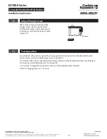
When door is closed against top strike, 
plunger screw releases top latch and 
bottom bolt. Adjust so that when door is 
shut tight, screw head just touches strike. 
(Figure 20)

12

Adjust Plunger Screw

Just Touch

Figure 20  

Summary of Contents for Corbin Russwin ED7800 Series

Page 1: ...nd Egress Hardware Group Inc is prohibited FM466 04 20 For installation assistance contact Corbin Russwin 1 800 543 3658 techsupport corbinrusswin assaabloy com WARNING This product can expose you to...

Page 2: ...e Group Inc is prohibited For installation assistance contact Corbin Russwin 1 800 543 3658 techsupport corbinrusswin assaabloy com TOC Table of Contents 1 Components 3 2 Pre Installation 4 3 Prepare...

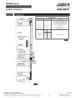
Page 3: ...ke Mounting Bracket Bottom Bolt Tension Spring Bottom Bolt Operating Tube Screw Tenon Dogging Key Felt Deadener Dogging Hole Cotter Pin Hole Lifting Flange for Active Case Active Case Outside Operator...

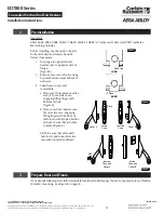
Page 4: ...over A Lift Figure 3 3 Prepare Door and Frame If not already fully prepared follow template furnished and drawings shown for exposed screw or hidden bracket mounting See Figure 6 on page 5 Figure 4 Fi...

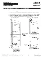
Page 5: ...ct top latch by holding case and pushing up on rod Insert top latch rod into top of stile and into bottom tube Secure with screws indicated in chart Figure 2 on page 3 4 Insert Rods and Secure Top Lat...

Page 6: ...cases are level at same height Figure 9 2 Drill and tap for No 1 4 20 screws 3 Mount cases 8 Install Inactive Case Figure 7 1 Undog cases Using key furnished back out screw and remove tenon from acti...

Page 7: ...crossbar over tenon secured to inactive case lever Figure 12 NOTE If crossbar will not slide over tenon loosen screw slightly and tap head of screw with mallet 4 Set other end of crossbar into recess...

Page 8: ...ll Strikes Top Strike Door C L of Bottom Bolt Backset Figure 15 1 Following template furnished mark bolt backset on outside of door 2 Press in top latch plunger screw to project top latch and bottom b...

Page 9: ...When door is opened by turning operator latch top latch and bottom bolt should retract and stay retracted until plunger screw is pushed in From Inside When door is opened by depressing crossbar top la...

Page 10: ...ASSA ABLOY Access and Egress Hardware Group Inc All rights reserved Reproduction in whole or in part without the express written permission of ASSA ABLOY Access and Egress Hardware Group Inc is prohib...

Page 11: ...ASSA ABLOY Access and Egress Hardware Group Inc All rights reserved Reproduction in whole or in part without the express written permission of ASSA ABLOY Access and Egress Hardware Group Inc is prohib...

Page 12: ...l rights reserved Reproduction in whole or in part without the express written permission of ASSA ABLOY Access and Egress Hardware Group Inc is prohibited For installation assistance contact Corbin Ru...

Reviews: