background image

14

IN100  Cylindrical Lock

Copyright © 2016 Corbin Russwin, Inc., an ASSA ABLOY Group company. 

All rights reserved. Reproduction in whole or in part without the 

express written permission of Corbin Russwin, Inc. is prohibited.

5) Installation Instructions (Continued)

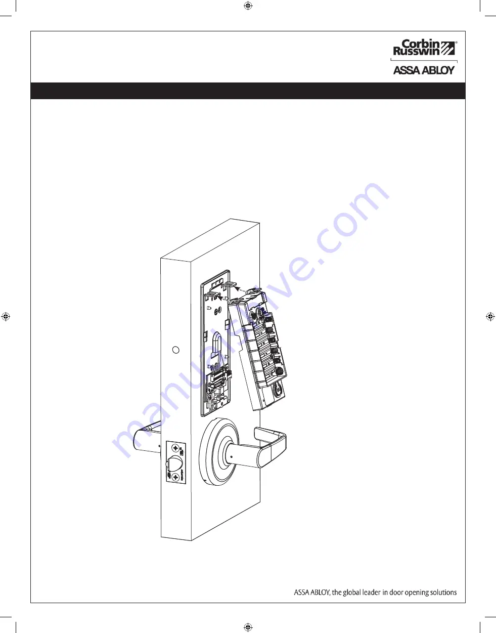
11.         Installation of Inside Component Assembly

a. Insert top tabs of controller into slots on mounting plate (Fig. 11).
b. Ensure proper alignment of board-to-board connectors while pivoting bottom of controller        

    toward door until tab on bottom snaps securely into place on mounting plate.  

CAUTION: To avoid possible damage to board-to-board connectors,  

                  care should be taken when securing controller to mounting  

                  plate. If there is resistance when securing, detach controller  

                to determine cause before re-attaching controller.

Fig.  11

Inside Face of 

Door

Summary of Contents for Corbin Russwin IN100

Page 1: ...factory warranty Important The accuracy of the door preparation is critical for proper functioning and security of this lock Misalignment can cause premature wear and a lessening of security For Technical Assistance call Corbin Russwin at 1 800 810 WIRE 9473 Copyright 2016 Corbin Russwin Inc an ASSA ABLOY Group company All rights reserved Reproduction in whole or in part without the express writte...

Page 2: ...t on a circuit different from that to which the receiver is connected Consult the dealer or an experienced technician for help The term IC before the radio certification number only signifies that Industry Canada technical specifications were met This Class B digital apparatus meets all requirements of the Canadian Interference Causing Equipment Regulations Operation is subject to the following tw...

Page 3: ...eries Corbin Russwin locks are designed with quality components to provide high security performance and durability To comply with Fire Listed doors the batteries must be replaced with alkaline batteries only Electronic Specifications For specific security information please contact your local ASSA ABLOY Door Security Solutions sales consultant or call 800 810 WIRE Input Power DC 9V 1 5A 6 AA alka...

Page 4: ...SS HID iCLASS SE SIO enabled HID iCLASS Seos HID MIFARE SE HID DESfire EV1 SE HID Prox NFC enabled mobile phones White with metal trim 1 IN 100 EM01CL33134 IPS B All credentials supported by the IP option plus MIFARE Classic and DESfire EV1 Black 1 IN 100 EM01CL33134 IPS W All credentials supported by the IP option plus MIFARE Classic and DESfire EV1 White 1 IN 100 EM01CL33134 IPS MB finish All cr...

Page 5: ... Allen Wrench supplied 1 785F628 CL33134 Cylindrical lock with fixed core cylinder 1 785F638 CL33134 Cylindrical lock with removable core cylinder 2 785F488 Inside Spring Cassette IN100 REX 1 3 4 2 Door 1 785F498 Inside Spring Cassette IN100 REX 2 1 4 Door 3 783F208 Outside Spring Cassette 1 4 820F609 DPS Door Position Switch Kit 1 For parts not listed refer to CL3300 Parts and Service Manual 4 Pr...

Page 6: ...B Illustrations shown are as viewed from the outside or secure side of opening Prep door according to supplied door marker FM356 For door manufacturer templates visit www corbinrusswin com and reference template T31203 Outside Face of Door Inside Face of Door 1 Verify Hand and Bevel of door 2 Door Preparation Wood Door shown Fig 2 Through bolt Hole Raceway for Optional Remote Power Through bolt Ho...
Page 7: ...ch Bolt a Insert DPS into the raceway on the latch edge of the door b Push wires through raceway toward lock prep c Push DPS firmly into place by hand Note DO NOT TAP SWITCH WITH ANY TOOL d Install magnet into door frame Push firmly into place by hand See instruction A7983A 3 Install Door Position Switch DPS CAUTION if DPS is not installed or is installed improperly door status monitoring features...

Page 8: ...r 6 a Feed lock body and wire through 2 1 8 diameter hole from outside of door Fig 6a Engage latch with lock body Latch ears must slide into housing as shown Fig 6b 6 Install Lock Body Fig 6c Inside Face of Door Spring Cassette b Connect 4 pin connector from lock body to 4 pin on cassette Fig 6c c Temporarily install top throughbolt to hold chassis in door Fig 6c Important Door must remain open du...
Page 9: ...without the express written permission of Corbin Russwin Inc is prohibited 7 Install Inside Spring Cassette Lock 5 Installation Instructions Continued a Feed harness wires and ground wire up through raceway Fig 7a b Remove screw from previous step c Slide on cassette and secure with 2 screws Fig 7b Fig 7a Spring Cassette Remove Screw Fig 7b ...

Page 10: ... Inc an ASSA ABLOY Group company All rights reserved Reproduction in whole or in part without the express written permission of Corbin Russwin Inc is prohibited 5 Installation Instructions Continued 8 Installation and Removal of Lever and Standard Cylinder ...

Page 11: ...on Instructions Continued Fig 9a Outside Face of Door 9 Install Outside Reader Escutcheon and Inside Mounting Plate LED Reader Assembly with Harness a Orient the reader so the LED lens is at the top b Feed reader harness through door from outside to inside c Install the reader to the outside of door by aligning the mounting posts with the door preparation holes Hold the reader flush against door w...

Page 12: ...t if required See Figure 9b IMPORTANT Do not run wires through bottom flange hole in plate Fig 9b c it will damage wires and the controller connector Route wires around flange do not route wires through the flange hole Fig 9c 5 Installation Instructions Continued Fig 9b Gasket Mounting Plate Lock body Harness Ground Lug DPS Reader Harness NOTE Cable lengths exaggerated for illustrative purposes In...

Page 13: ... IMPORTANT Do not run wires through bottom hole in plate it will damage wires and the controller connector Route wires around flange do not route wires through the flange hole Fig 10B D E Secure the 24 pin card reader connector Fig 10F Ground Lug DPS 4 pin A Lock Body 10 pin Fig 10D B Reader 24 pin Board to Board Connector Fig 10F D D Secure the mounting assembly while ensuring proper alignment of...

Page 14: ...bly a Insert top tabs of controller into slots on mounting plate Fig 11 b Ensure proper alignment of board to board connectors while pivoting bottom of controller toward door until tab on bottom snaps securely into place on mounting plate CAUTION To avoid possible damage to board to board connectors care should be taken when securing controller to mounting plate If there is resistance when securin...

Page 15: ...ully press bottom of cover toward door without pinching or damaging wires c Secure cover utilizing security allen wrench provided 5 Installation Instructions Continued 12 Battery Installation Inside Cover Security Allen Screw 13 Inside Cover Installation Fig 12 Fig 13 1 Place 6 AA alkaline batteries in the compartment being careful to align polarity properly Fig 12 2 After batteries are installed ...

Page 16: ...n against lock case wire harness or any other obstructions c Check that the key retracts the latch d The key should rotate freely e Try the inside lever ensure it retracts latch f Present a valid credential Fig 14b to unlock outside lever turn lever handle to ensure latch retracts Fig 14a Fig 14b When lock is fully installed perform the following steps Note The credential should approach the inscr...

Page 17: ...sh offline EAC offline Aperio lock and Green three red flashes EAC offline UHF Yellow off fast flash communication Some special LED indication schemes are used during lock maintenance actions 2 sec Figure 2 Communication hub maintenance LED indication Pairing active Yellow green Ethernet LED indication The LED on the AH40 communication hub indicates both the status of the Ethernet link level and e...

Page 18: ...yellow flashes 25 seconds every second Access denied Three red flashes 5 second each EAC offline Lock mechanism is Continuous red flashes blocked when closing 125 seconds every 1 sec Error in lock Ten red flashes 125 sec each maintenance required Repeated every 10 sec if lock can t close Ten red flashes 125 sec each repeated every 10 sec Tamper Time to replace Continuous yellow flashes 25 seconds ...

Page 19: ...ery Figure 6 Lock POST LED indication 8 3 3 Test fail 1 red 1s 3 blinks 5 sec green or red at least one test failed red see table below FATAL ERROR CABLE ERROR MECHANICAL ERROR FATAL ERROR Tests core functionality MCUs memory and internal communication etc CABLE ERROR Tests communication between the different parts in the system i e different boards connected with a wire MECHANICAL ERROR Test rela...

Page 20: ...Copyright 2016 Corbin Russwin Inc an ASSA ABLOY Group company All rights reserved Reproduction in whole or in part without the express written permission of Corbin Russwin Inc is prohibited ...

Reviews: