37
The warranty on Corbin Russwin products becomes void if the product is modified in any way, regardless of whether the modifications causes or contributes to any alleged defect. If a
Corbin Russwin product is modified it may no longer meet industry certification and quality control standards applicable to the original product and is no longer a genuine Corbin Russwin product.
Copyright © 1999-2018, ASSA ABLOY Access and Egress Hardware Group, Inc. All rights reserved. Reproduction in whole or in part without the express written permission of ASSA ABLOY Access
and Egress Hardware Group, Inc. is prohibited. Patent pending and/or patent www.assaabloydss.com/patents.
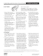
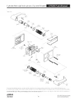
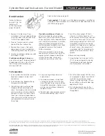
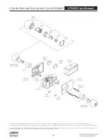
Cylinder Removal Instructions (Discontinued Models)
UT5200 Parts Manual
For Corbin 700/Russwin 1600 Series “Baby” Unit Lock- Horizontal Keyway
Tools needed: 1/8” and 1/4” flat blade screwdrivers, needle nose pliers and a plastic or rawhide mallet.
Caution!
No replacement parts are available for this lock. Be very careful not to damage or distort any parts.
1. Remove all escutcheon screws or thru-
bolts above and below knob on both
sides of door. Loosen thru-bolt on
inside near latch. Pull lock from edge
of door.
2. Remove chassis cover. Gently pry
edges loose with small screwdriver
while pulling cover away from chassis.
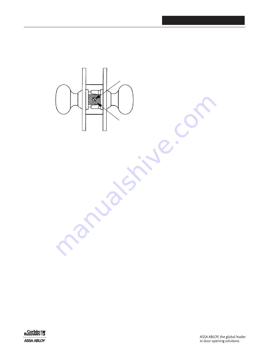
3. Observe exposed mechanism on end
of chassis OPPOSITE latch bolt. For
this model, one or two screws pass
through a bracket-shaped steel knob
retainer. If chassis is not constructed
this way, you are reading wrong set of
instructions.
Before removing bracket screw(s), turn
knob(s) and observe orientation of
hubs and any other small parts
directly connected with knob shanks.
These parts may fall out when knob(s)
are removed and you will need to
reinstall them correctly. Make sketch
if desired.
Depending on function of lock,
unlock knob with inside turn button
or by using key. This is not be possible
on storeroom function with rigid
outside knob.
4. Remove bracket screw(s). On
reassembly, test all operations of both
knobs before reinstalling screw(s).
5. To avoid spilling parts from chassis,
grasp lockset by escutcheons and
stand it on knob which will remain
in place. Support lockset so
escutcheons are parallel with work
surface, and knob to be removed
faces up.
6. Note orientation of keyway for proper
handing during reassembly. Remove
bracket and slowly pull knob off.
7. Remove cap from back of knob. If
loose, it may have remained on trim as
knob was removed. If stuck, rap end
of knob shank (
not cap!
) with plastic
or rawhide mallet to jar cap loose.
If it has become sealed in place by
paint, lacquer or brass polish, it may
be necessary to pry it loose with small
screwdriver.
8. Remove shank screws which are now
exposed. Older model has two screws
and newer model has one screw.
9. Unscrew shank from knob and remove
cylinder. If stuck, place screwdriver
shaft across slot in end of knob shank
to turn. On reassembly, be sure screw
hole(s) in knob shank align with holes
in knob before installing screws.
10. If cylinder must be dismantled, drive
out actuator retaining pin. This pin
also serves as plug retainer. LEAVE
KEYS OUT of cylinder until you are
ready to rekey it.
Caution: If you are rekeying several
of these cylinders, keep all major
components of each cylinder
together. Mixing parts may result in
end play of plug, making it necessary
to “pinch” key to remove it.
Most cylinders used in these locks
are master ring cylinders with X Class
keyways with .509" diameter plugs.
Refer to Corbin Russwin Cylinder
Manual for cylinder combinating
instructions, including all pin lengths
and key bitting specifications.
11. Clean all parts, including inside of
knob shank hole in escutcheon, and
reverse these steps for reassembly.
Use only dry powdered graphite to
lubricate cylinder. Lubricate lockset
parts as required.
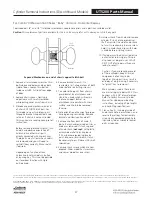
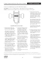
Exposed Mechanism on end of chassis opposite latchbolt
1 or 2
Screws
Bracket


