3
80-9330-3005-152 04/18
DC3210 Series Closer
A2, A4 or A5 Heavy Duty Parallel Arm
Installation Instructions
Copyright © 2018 Corbin Russwin, Inc., an ASSA ABLOY Group company.
All rights reserved. Reproduction in whole or in part without the express written
permission of Corbin Russwin, Inc. is prohibited.
For installation assistance contact Corbin Russwin
1-800-543-3658 • techsupport.corbinrusswin@assaabloy.com
2
Installation
1. Template
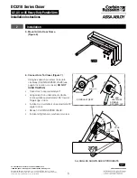
Mark and prepare door and jamb (for closer
bracket and arm bracket). Use template and
dimensions charted. (Figure 2)
NOTES:
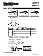
• Check hand of door. (Figure 1)
• Right Hand Application Shown,
Left Hand Opposite
• Dimensions given in inches (mm).
Do Not Scale Drawing.
• Closer must be installed in a true
horizontal plane to ensure proper closer
performance.
Figure 2
Opening
Maximum
DIM. A
DIM. B
DIM. C
Minimum
85°
13-3/4"
(349)
12-9/16"
(319)
28-3/4"
(730)
90°
12-13/16"
(325)
11-5/8"
(295)
27-7/8"
(708)
100°
11-1/4"
(286)
10-1/16
(256)
26-1/4"
(667)
110°
9-15/16"
(252)
8-3/4"
(222)
25"
(635)
5/8
(16)
2-5/8
(60)
FRAME STOP
TOP OF DOOR
CL
HINGE
OR
PIVOT
DOOR
FRAME STOP
2-3/4
(70)
5/8
(16)
1-1/2
(38.1)
1/4
(6.35)
CLOSER
BRACKET
1
(25.4)
4-5/16
(109.5)
B
A
C
TYP.
15/16
(23.8)
3/4
(19)
1-3/8
(35)
Minimum Clearance
2
(50.8)
2
(50.8)
2
(50.8)
1
(25.4)
1-1/2
(38.1)
SEE MOUNTING SCREW
SPECIFICATIONS
NOTE: ANGLE SUPPORT MUST BE
DRILLED AND TAPPED IN THE FIELD
447F14
DOOR
FRAME
M85 OPTION 447F14
ANGLE SUPPORT BRACKET
5/8
(16)
REF.
DOOR
FRAME
ARM
BRACKET
SPACER BLOCK
(When required)


