7
1-800-727-5477 • www.sargentlock.com
Copyright © 2006-2010, 2022 SARGENT Manufacturing Company. All rights reserved. Reproduction in whole or in
part without the express written permission of SARGENT Manufacturing Company is prohibited. Patent pending
and/or patent www.assaabloydss.com/patents.
A7827E 6/22
FM8700, 12-FM8700
Installation Instructions Manual
Surface Vertical Rod Exit Device
P OS ITION TR IM ON
DOOR - Align spindle
with B E L L HOUS ING
THR U-B OLT C HAS S IS
to E T TR IM with
(2) 1/4" -20 x 2 3/8"
P H.F L .HD.Mach. S crews
C hassis
Bell housing
6
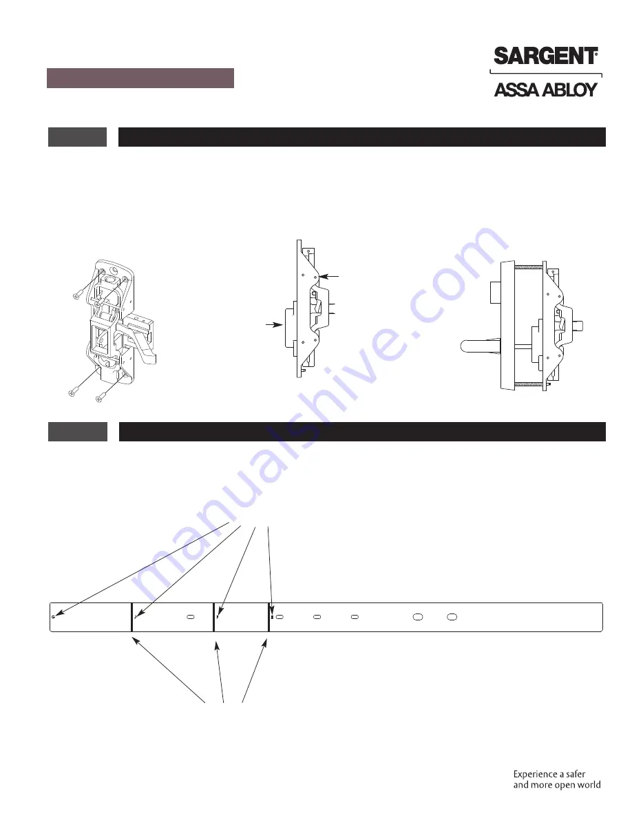
Install Center Chassis
1. Secure Chassis and Chassis Shim with (4) #10-24 x 3/4" Phillips Head Flat H.D. Machine Screws, 4 corner
mounting holes.
Note:
Use all four screws provided.
7
Rail Shim Lengths and cutting Instructions
1. Refer to rail size listed on the box the device was shipped in. Break Rail Shim to the length that corresponds to
the rail size.
Note:
If shim needs to be cut, always cut shim from the end closest to the hinge edge.
R ail S izes
Use Breaking L ines to shorten S him to the needed R ail size


