0 #
SARGENT
4
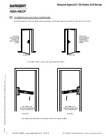
Installation Instructions
1. Determine locations of components at the door
2. Mount all hardware and peripheral equipment according to manufacturer’s instructions
NOTE: For exit device mechanical installation, refer to mechanical instruction sheets and
templates included with product.
3. Power supply should be mounted near door to avoid power drop due to excessive wire runs
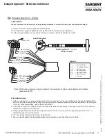
4. Features used will determine wire requirements of electric hinge or other power transfer
8
*
7
9
2
5
4
6
3
1
Sample Elevation Diagram
REMOTE RESET
(Optional)
7
Electromagnetic
Lock
02/29/16
1-800-810-WIRE • www.sargentlock.com • A7743E 5
Copyright © 2016, Sargen
t Manufacturing Company
, an A
SS
A AB
LO
Y G
roup company
. All right
s reser
ved
.
Reproductions in whole or in par
t without express writ
ten permission of Sargen
t Manufacturing Company is prohibited
.
Delayed Egress 57- 80 Series Exit Device


