background image

26          1-800-810-WIRE • www.sargentlock.com • A8151H 

Copyright © 2016, 2019, 2021, Sargent Manufacturing Company

, an ASSA ABLOY Group company

. All rights reser

ved. 

Reproductions in whole or in part without express written permission of Sargent Manufacturing Company is prohibited.

04/30/21

IN120 / IN220 Mortise Lock  

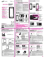
14  Inside Cover Installation

1.  Assemble cover by hooking top edge on inside mounting plate taking care not to pinch gasket 

(top edge goes between plate and gasket).

2.  Carefully press bottom of cover toward door without pinching any wires.
3.  Secure the cover with a security allen wrench (Fig. 14B).

Security    
Allen Screw

Fig. 14A

Fig. 16B

Fig. 14C

*Note location of installed ferrite bead (IN220 PoE) and excess wires (Fig. 14A, D).

Fig. 14D

Summary of Contents for SARGENT IN Series

Page 1: ...ASSA ABLOY Group company All rights reserved Reproduction in whole or in part without the express written permission of Sargent Manufacturing Company is prohibited Mortise Lock Installation Instructions IN Series IN120 Wi Fi IN220 PoE Mortise Lock Installation Instructions ...

Page 2: ...xpress written permission of Sargent Manufacturing Company is prohibited 04 30 21 IN120 IN220 Mortise Lock 1 2 3 4 5 6 7 Table of Contents Warning 3 Regulatory Power Specifications 4 General Description 5 Hardware Specifications 5 Technical Specifications 5 Parts Breakdown 6 Installation Wiring 8 Door Preparation Lock Installation 12 Installation Instructions 15 Operational Check 27 8 9 10 ...

Page 3: ...ception which can be determined by turning the equipment off and on the user is encouraged to try to correct the interference by one or more of the following measures Reorient or relocate the receiving antenna Increase the separation between the equipment and receiver Connect the equipment into an outlet on a circuit different from that to which the receiver is connected Consult the dealer or an e...

Page 4: ...es must be replaced with alkaline batteries only Optional Hard Power UL 294 Listed Power Supply Required 9 24VDC 300mA UL 294 Access Control Ratings Destructive Attack Level 1 Line Security Level 1 Endurance Level 4 Standby Power Level 1 Compliance with IEEE 802 3 at or af specifications was not verified as part of UL 294 B IN120 Wi Fi version For Mobile Credential Enabled versions of this electro...

Page 5: ...vidng heightened identity security and multiple credentials including mobile access The IN120 mortise lock uses IEEE 802 11 Wi Fi communication and a flexible feature set for easier more cost effective installations allowing facilities to leverage their IT infrastructure to expand access control coverage to more doors With the energy efficiency and streamlined architecture of Power over Ethernet P...

Page 6: ...bited 04 30 21 IN120 IN220 Mortise Lock Parts Breakdown 6 Tools Required 2 Phillips screwdriver Flat head screwdriver Security allen wrench Consult catalog for electronic replacement part numbers 1 4 5 3a 3b 2 ITEM No DESCRIPTION 1 Outside Escutcheon Assembly 2 Inside Mounting Plate Assembly includes Gasket 3a PoE Controller Assembly 3b Wi Fi Controller Assembly batteries included 4 Inside Escutch...

Page 7: ...20 82276 hand fin Lock body with deadbolt with cylinder IN 120 82277 hand fin Lock body with deadbolt without cylinder IN 120 82278 hand fin Lock body without deadbolt with cylinder IN 120 82279 hand fin Lock body without deadbolt without cylinder 4 82 3211 Inside Trim Pack Standard Levers 1 82 5357 Inside Trim Pack Deco levers shown 1 5 Consult Factory Inside Lever 1 6 79 0035 Lock front 7900 Wit...

Page 8: ...prohibited 04 30 21 IN120 IN220 Mortise Lock SARGENT IN220 PoE Typical Application A PoE frame harness assembly B PoE data hinge from McKinney C PoE door harness from McKinney D IN220 PoE Lock E For locks with external DPS Door Position Switch Door width determines length Network Cable Network Switch 802 3af Surface Mount RJ45 B C E D A B B C D E Installation Wiring Overview Installation Wiring fo...

Page 9: ...und in 15 Frame Harness Cable drain wire concealed in shrink tubing Patch Panel Drain Wire Terminated on Rack Cable Cat 5e or higher 24 AWG RJ45 F Jack Approved Software Certified Integrator CI supplies and terminates the B Splice connector and the male RJ45 connector from harness to end user provided facility cable Supplied by End User PoE Switch PoE Switch is Terminated to Earth Ground Patch Cab...

Page 10: ...re for Earth Ground in 15 Frame Harness Cable drain wire concealed in shrink tubing Frame Harness Installation Hinge side of PoE Frame harness 4 pin M 6 pin M Frame PoE Hinge PoE Data Hinge Hinge side harness connectors 4 pin female molex connector 6 pin female molex connector with ground wire Lock side harness connectors 4 pin female molex connector 6 pin female molex connector with ground wire B...

Page 11: ...h door Notes Connectors go on only one way They cannot be plugged to incorrect position Do not force and do not offset connectors Be sure they are completely seated flush Order of installation may vary Refer to appropriate sections for instructions 1 Prop door open 2 Using the ring terminal carefully route the assembly through the door channel toward lock PoE Door Harness IN220 PoE Lock 4 pin F 4 ...

Page 12: ...are Door Door Preparation Lock Installation 8 B Door Preparation Prior to installation all holes must be free of burrs debris and sharp edges Prepare door according to appropriate template see website www intelligentopenings com Field Template A8150 ships with product Door Manufacturer s Template 4713 Outside Cylinder Hole only with cylinder installation Outside of Door Inside of Door Cable Hole L...

Page 13: ... of door To rotate locking piece Fig 2A1 a Position lock body with red surface of locking piece visible b Insert blade type screwdriver into locking piece slot to rotate lock ing piece toward back of lock body c Rotate the locking piece 180 until RED surface is on opposite side Note Red indicates locked side outside If 7900 is type of lock being installed 2 Prepare Lock Body Inside of Door 3 Insta...

Page 14: ...slot to rotate locking piece toward back of lock body c Rotate the locking piece 180 until RED surface is on opposite side Note Red indicates locked side outside Fig 2B1 Locking Guide Slot Red color indicates locked side Push In Right Hand Lock Shown 1 Reverse Lock Hand If Required If 8200 is type of lock being installed Beveled surface of latch must face strike Fig 2B2 The deadlatch is self adjus...

Page 15: ...e lock body into the pocket while lightly applying tension to the wire harness Fig 1 2 12 24 screws Inside of Door Wire Harness Note Do not pull the lock into the pocket using the harness alone Ensure that the wire harness is not pinched between the lock and the mortise pocket 3 Insert 2 12 24 screws into the lock body Fig 1 and tighten with a screw driver Do not fully tighten until cylinder and l...

Page 16: ...rect Fig 2B 1 Slide the spring and the rosette onto the cylinder Fig 2A 2 Rotate the cylinder into cylinder hole with fingers 3 Insert key 75 of the way and utilize the key to rotate the cylinder into the rest of the cylinder hole Note Do not attempt to tighten all the way 4 Verify that orientation of cylinder has the SARGENT logo as depicted in Figure 2B 5 Hand tighten the cylinder clamp screw wi...

Page 17: ...nd lock body Make certain the lever spindle is properly engaged inside the lock body Fig 3A 2 On the inside of the door insert spindle into square hole of mortise lock Fig 3B 3 Slide inside adapter and plate assembly over spindle and secure with 2 8 32 X 5 8 Phillips oval head and lock washer machine screws Inside of Door Outside of Door DPS Fig 3B Fig 3A Wire Harness From Lock Body Spindle Spindl...

Page 18: ... threads then clockwise to securely tighten 2 Slide lever onto spindle until fully seated Be sure handle is horizontal and facing the hinge side of the door Push lever onto spindle so minimum gap is visible 3 Tighten the set screw securely with a T20 Torx driver 4 Finish securely tightening 2 12 24 lock body screws 5 Before closing the door test that the lever is functional and ensure smooth opera...

Page 19: ...Insert thumb turn into preparation hole and engage slot in lock body 2 Orient mounting plate so screw hole is vertical and aligned with preparation holes 3 Secure plate with Phillips screw provided 4 Test thumb turn for function by retracting and projecting the deadbolt 7976 7977 and 82276 82277 functions only 6 Attach Front Plate Attach front plate with 2 Phillips head screws Outside of Door Fig ...

Page 20: ...ng Company is prohibited 04 30 21 IN120 IN220 Mortise Lock 7 Install IN120 IN220 Outside Reader 1 Orient the reader so the LED lens is at the top 2 Feed the reader harness through the door from outside to inside 3 Install the reader to the outside of door by aligning the mounting posts with the door preparation holes Hold the reader flush against door while ensuring proper alignment Fig 7A LED Rea...

Page 21: ... partially tighten the 2 through bolts on the inside of the door to secure the reader Fig 8A NOTE Cable lengths exaggerated for illustrative purposes Gasket is required for all installations Separate gasket from mounting plate to feed cables connectors through holes as indicated Fig 8A Once cables connectors are fed through reattach gasket to mounting plate Gasket Inside Mounting Plate Fig 8A Insi...

Page 22: ...n Board to Board Connector Fig 10A C A B IMPORTANT Do not run wires through bottom hole in plate Fig 9 it will damage wires and the controller connector Route wires around flange do not route wires through the flange hole Fig 9 9 Preparation of Connectors CAUTION Do not touch or allow debris to enter connector contacts Fig 9 Supplied tube contains 5 grams of silicone dielectric compound grease Eve...

Page 23: ...o RJ45 M Connector PoE only RJ45 M Fig 10C Feed wires thru ferrite bead PoE only E Pull 5 1 2 inches of Ethernet cable from hole Strip cable jacket back 3 1 2 inches F Separate untwist and straighten 8 Ethernet wires before carefully feeding through ferrite bead Fig 3D G Crimp RJ45 male connector on end of wires 11 Installing the Controller Important Note Before you install the controller Fig 11A ...

Page 24: ...until two tabs on top click securely into place on mounting plate Fig 11D CAUTION To avoid possible damage to board to board connectors care should be taken when securing controller to mounting plate If there is resistance when securing detach controller to determine cause before re attaching controller Fig 11D 12 Supplying Power to the Controller 1 Once controller is securely in place connect PoE...

Page 25: ...ng care not to pinch gasket top edge goes between plate and gasket 2 Carefully press bottom of cover toward door without pinching any wires 3 Secure the cover with a security allen wrench Fig 13B B IN120 WIFI 1 Once controller is securely in place place 6 AA alkaline batteries in the compartment being care ful to align polarity properly 2 After batteries are installed there is a slight delay then ...

Page 26: ...bited 04 30 21 IN120 IN220 Mortise Lock 14 Inside Cover Installation 1 Assemble cover by hooking top edge on inside mounting plate taking care not to pinch gasket top edge goes between plate and gasket 2 Carefully press bottom of cover toward door without pinching any wires 3 Secure the cover with a security allen wrench Fig 14B Security Allen Screw Fig 14A Fig 16B Fig 14C Note location of install...

Page 27: ... key retracts the latch the key should rotate freely 3 Throw the deadbolt if present Check that the key retracts both the deadbolt and the latch 4 Try the inside lever Ensure it retracts latch and deadbolt if installed 5 Use a valid credential set up with the Lock Configuration Tool to unlock outside lever and retract latch Refer to Lock Configuration Tool user manual WFMN1 for information on how ...

Page 28: ...ications The company s customer base includes commercial construction institutional and industrial markets Copyright 2016 2019 2021 Sargent Manufacturing Company an ASSA ABLOY Group company All rights reserved Reproduction in whole or in part without the express written permission of Sargent Manufacturing Company is prohibited Sargent Manufacturing Company New Haven CT 2019 Patent pending and or p...

Reviews: