1-800-810-WIRE • www.sargentlock.com • A8185D
Copyright © 2016, 2019, 2021, Sargent Manufacturing Company
, an ASSA ABLOY Group company
. All rights reser
ved.
Reproductions in whole or in part without express written permission of Sargent Manufacturing Company is prohibited.
04/30/21
IN120 / IN220 Exit Device
22
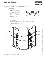
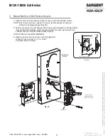
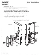
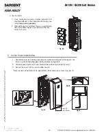
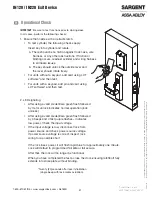
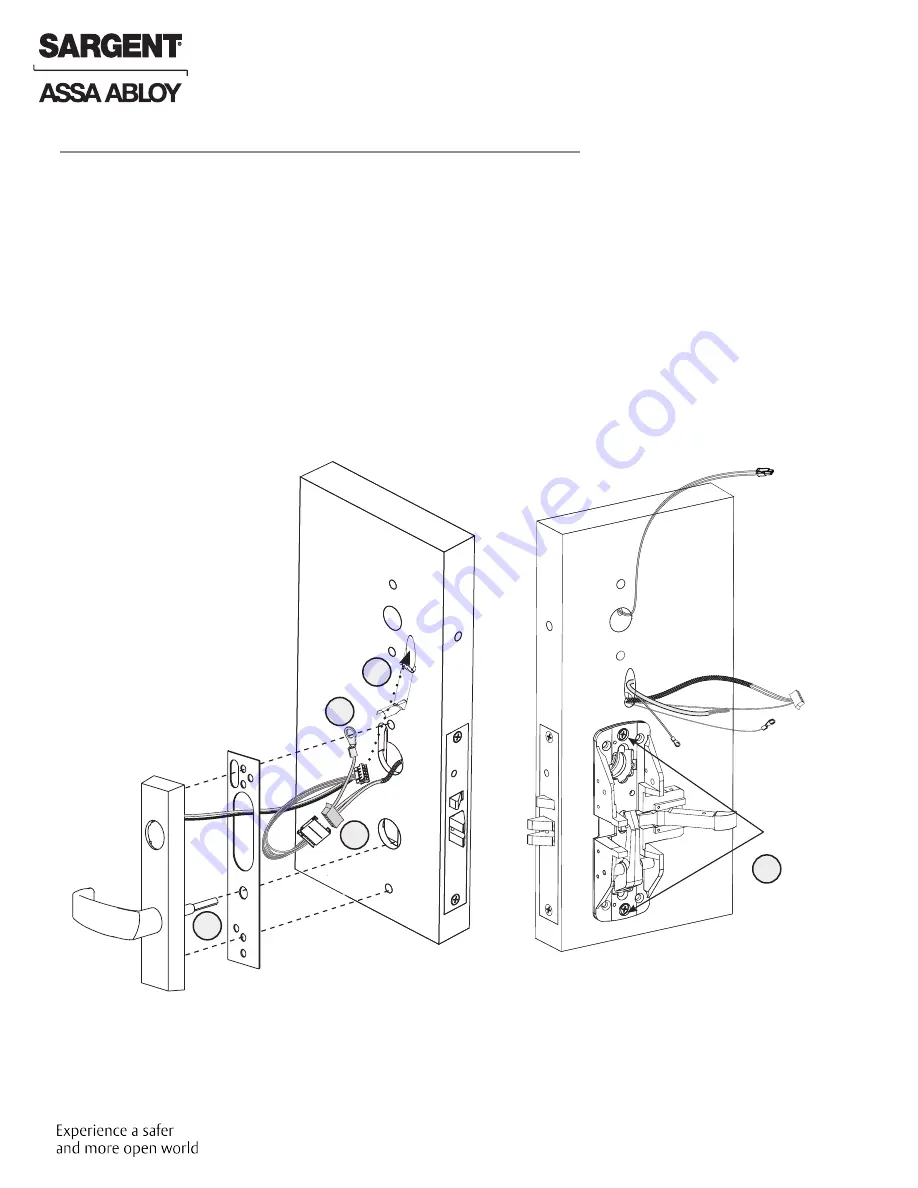
A. Connect motor harness adapter to chassis harness connector (Fig. 4A).
B. For wood doors: Route ET wire harness connector through the cylinder hole,
up and through the wire run channel to the controller cutout.
For metal doors: Route ET wire harness through the cylinder hole out the
controller cutout.
C. Pass top ET trim mounting post through chassis harness ground lug.
D. Ensure ET spindle engages the lower hub of the exit chassis.
E. Fully tighten (2) chassis through bolts (Fig. 4B).
NOTE: Cable lengths exaggerated for illustrative purposes
4 Position Exit Trim (ET)
A
B
C
D
E
Fig. 4A
Outside of Door
Inside of Door
Tighten
fully
Fig. 4B
NOTE: For exterior applications, use ET gasket (52-0263) as a seal between
ET escutcheon and outside door surface.


