Copyright © 2020, Sargent Manufacturing Company
, an ASSA ABLOY Group company
. All rights reser
ved.
Reproductions in whole or in part without express written permission of Sargent Manufacturing Company is prohibited.
05/31/20
SE LP10 Mortise Lock
A8113H • 800-810-WIRE (9473) • www.sargentlock.com
18
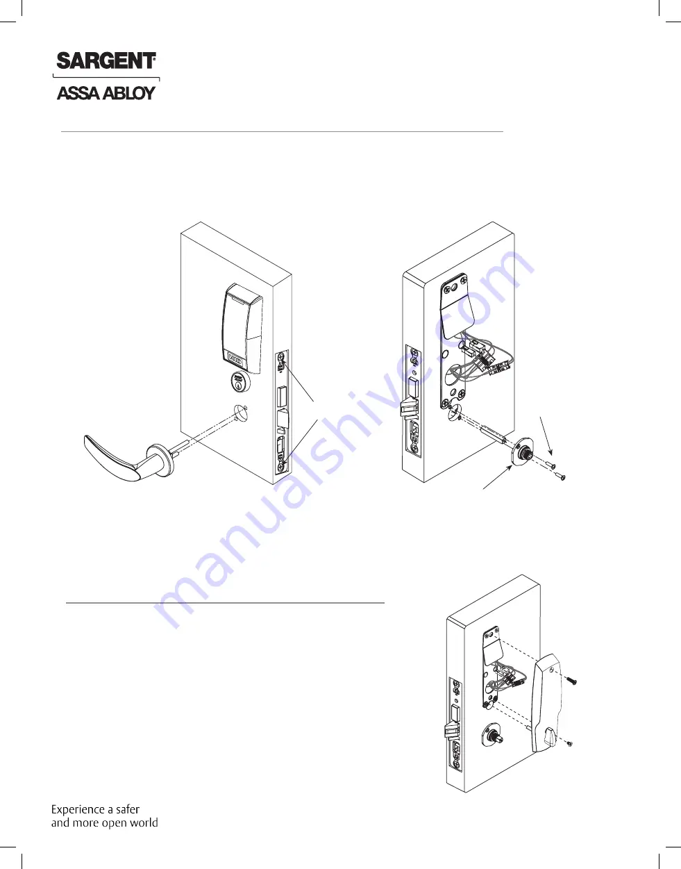
A. Carefully and neatly fold back lock body wires.
B. For locks equipped with deadbolts, align inside
escutcheon turn lever with slot in lock body. Adjust wires
as necessary to ensure that they are clear of inside
escutcheon. Seat inside escutcheon against door.
C. Tighten the inside escutcheon securely to the mounting
plate with the Phillips flat head machine screws provided.
Use 8- 32 x 5/8” for the top of the escutcheon and the
8-32 x 1/4” screws for the bottom of the escutcheon
located under the turn lever.
D. Be sure turn assembly and deadbolt function properly.
12 Install Inside Escutcheon Assembly
Fig. 11B
Fig. 11A
8-32 X 5/8”
Phillips Oval
Head and
Lock Washer
Machine
Screws
Inside of
Door
Outside of
Door
11 Inside Outside Lever and Inside Adapter Plate Assembly
Lock Body
Screw
Fig. 12
A. With outside lever horizontal, insert mounting posts through outside of door and lock body.
Make certain the lever spindle is properly engaged inside the lock body (Fig 11A).
B. On the inside of the door, insert spindle into square hole of mortise lock (Fig 11B).
C. Slide inside adapter and plate assembly over spindle and secure with (2) 8-32 X 5/8” Phillips
oval head and lock washer machine screws.
NOTE: For 8200 Deco levers and all 7900 lever styles, ensure that position of set screw hole
on inside adapter is oriented to match location of hole in inside lever handle.
Also, ensure that slot in spindle is facing away from door (Fig. 11B), and is oriented to
match location of hole in inside lever handle.
Inside
Adapter
Inside
of Door


