PN#
500-10550
Page 6
Rev. D, 12/14
Table 1. Component Label, Name, Selection, and Position
Component Label
Component Name
Selection
Position
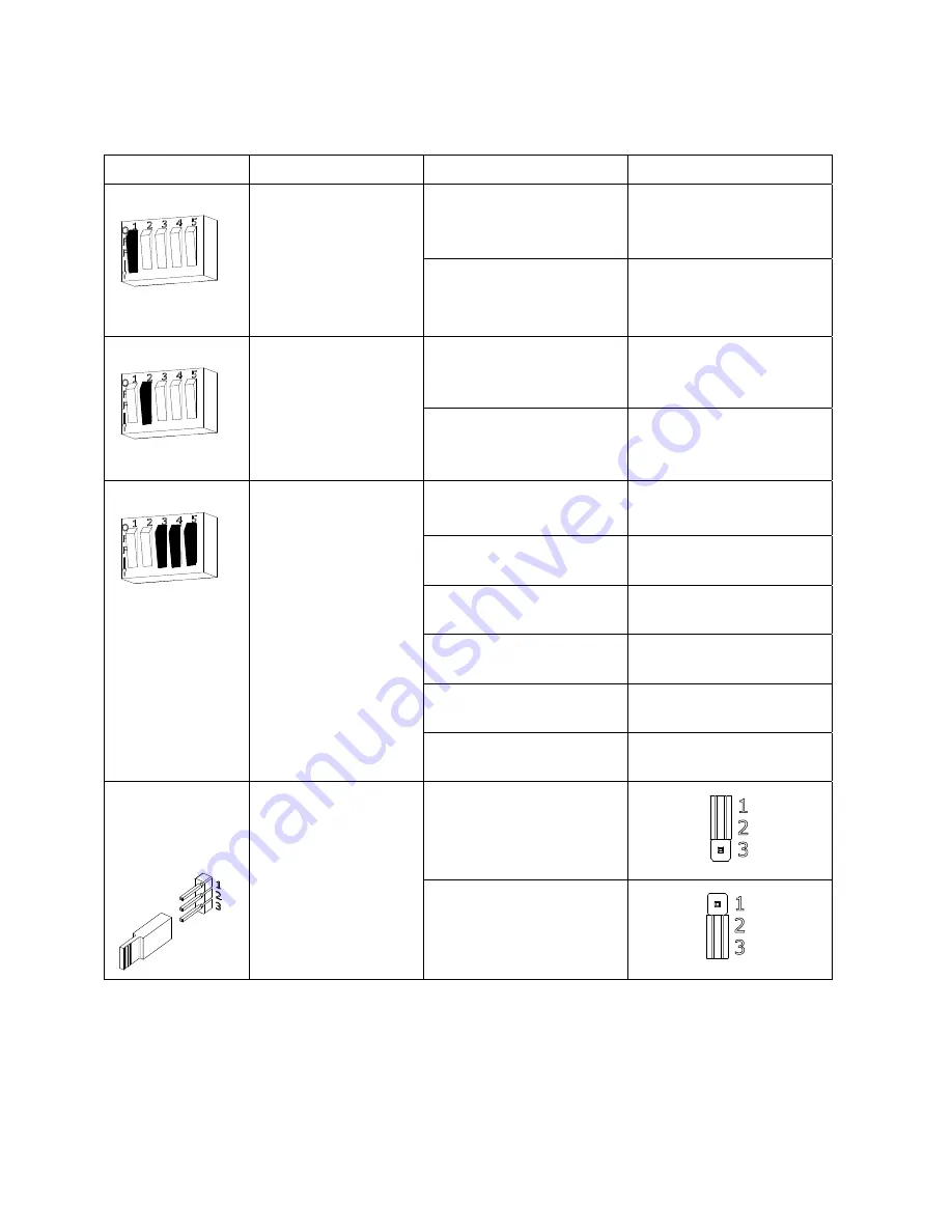
SW3
(M670 has a
2-position DIP)
DIP Switch SW3.1:
LED Enable
Position 1 setting of
the DIP switch enables
or disables the display
of the LED for lock
status.
ON = LED ENABLED
Position 1 ON (default)
OFF = LED DISABLED
(default setting)
Position 1 OFF
SW3
DIP Switch SW3.2:
LED Color Select
Position 2 setting of
the DIP switch controls
the color of the LED
output. Output options
are red or green.
ON = SECURE = RED
Position 2 ON
OFF = SECURE = GREEN
(default setting)
Position 2 OFF (default)
SW3
(Auto Relock
Timer available on
M680 models
only)
DIP Switch SW3.3,
SW3.4 and SW3.5:
Auto Relock Timer
Enable and Delay
Selection
The Auto Relock
Delay Timer is
disabled by default.
The delay can be
enabled by setting the
position 3 switch of
SW3 to ON, and then
selecting a time delay
with Position 4 and
Position 5 of SW3.
DISABLE Delay Timer
Position 3 OFF (default)
ENABLE Delay Timer
Position 3 ON
5 second delay
Position 4 OFF
Position 5 OFF
10 second delay
Position 4 OFF
Position 5 ON
20 second delay
Position 4 ON
Position 5 OFF
30 second delay
Position 4 ON
Position 5 ON
JP3
(available on
M680 models
only)
Jumper 3:
BondSTAT
Mode Select
A 3-pin jumper that
controls the output
setting for the
BondSTAT in Terminal
Block J1 Position 7 &
8.
(NC) Normally Closed
Circuit Closed when Bond
is secure (default setting)
(NO) Normally Open
Circuit Open when Bond is
secure


