background image

V9.7 01/05/20 

UD0011 

Page 160 of 177 

This Document is uncontrolled when printed unless over stamped “CONTROLLED DOCUMENT" 

Additional Information  

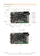
LED’s - There are two LEDs used to show status signals from the iMX28. Currently LED 2 is assigned to flash when the 

internal memory is being accessed. LED 1 is not currently used but available for future debug use. 


Relays Contact Specification - 2A 24V DC MAX (Resistive Load). 


Relay & Battery Fuses - If the relays or battery are wired into the control PCB incorrectly there are spare fuses that 
can handle an input for up to 15V. 

 
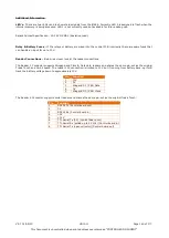
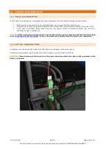
Reader Connections – Below is a closer look at the reader connections. 
 
The Reader 1 Connector supports Wiegand and Clock & Data card readers and shares the same pin-out as the original 

Traka Touch and 16-bit board. The reader 12V connection is limited to 12V but if running from battery back-up it will 

track the battery voltage down to approximately 10V. 


Pin 

Function  

12V  

5V  

Wiegand D1 / C&D Data  

0V  

Wiegand D0 / C&D Clock  

 
The Reader 2 Connector supports serial readers and shares the same pin-out as the original Traka Touch. 


Pin 

Function  

RS232 Tx (Control board out)  

0V  

RS232 Rx (Control board in)  

+5V  

+12V  

TTL Serial Tx (5V) (Control Board out)  

TTL Serial Rx (pulled up to 5V 10k) (Control board in)  

TTL Serial Tx (open collector) (Control board out)  


Summary of Contents for TRAKA UD0011

Page 1: ...cument is the subject of copyright and must not be copied or otherwise reproduced either in whole or in part without the express written permission of TRAKA TRAKA TOUCH USER GUIDE UD0011 01 05 20 VERS...

Page 2: ...cument 5 9 20 05 16 RC Relocation of Search in Traka Touch to Reports section Section 10 3 6 0 13 06 16 RC Added description of Fuel Distance Location Logging Section 17 7 6 1 15 06 16 RC Added descri...

Page 3: ...eport in section 10 9 0 10 04 19 RC Added information on User Roles to section 8 2 9 1 12 04 19 RC Added section for changing the certificates in the Traka Touch Root Store Section 11 8 9 2 12 06 19 R...

Page 4: ...inet Types 15 5 2 Cabinet Diagram 16 5 2 1 Cabinet Diagram Key 16 5 3 iFob Intelligent fob Key bunch Diagram 17 5 3 1 iFob Diagram Key 17 5 4 USB Memory Sticks 18 6 Overview 19 6 1 TrakaWEB 19 6 2 The...

Page 5: ...ning Items 50 10 1 Removing an Item 50 10 2 Override of an Empty Slot 52 10 3 Returning an Item 52 10 4 Item in Wrong Slot 52 10 5 No Door Systems 52 10 6 Non Locking Receptor Strips 53 10 7 Attaching...

Page 6: ...anguages for a User 93 12 12 3 Changing the Default Language of the System 94 12 13 Alarms 95 12 13 1 Table of Alarm Events 96 12 14 Curfews 97 12 14 1 Items with a Specific Time of the Day Curfew 97...

Page 7: ...System 126 14 2 1 Events 127 15 RRSS Random Return to Single System 128 15 1 System Requirements 128 15 2 RRSS Overview 128 15 3 Item Setup 128 15 4 Item Replacement 129 15 5 Granting Access to Items...

Page 8: ...witch 153 18 4 1 Accessing the system 153 18 4 2 Using the Override Key Switch 154 18 5 Serial Number Rating Plate Location 155 18 5 1 Traka Touch V 155 18 5 2 Traka Touch M 156 18 5 3 Traka Touch S T...

Page 9: ...V9 7 01 05 20 UD0011 Page 9 of 177 This Document is uncontrolled when printed unless over stamped CONTROLLED DOCUMENT...

Page 10: ...firm that its products have the functionality protection in place for an organisation to meet GDPR obligations including the fulfilment of the following rights to individuals please note that to fulfi...

Page 11: ...modation Equipment Asset Management and Control in Casinos Petrochemical Mining Airports Docks Railways Quarries Military and Emergency Services Traka Service Customer satisfaction is our top priority...

Page 12: ...cable Account Manager Name 2 Direct Contact Tel 2 Contact Email 2 Technical Support Help Desk Help Desk Direct Tel UK Telephone 0333 355 3641 International Telephone 0 44 333 355 3641 Help Desk Email...

Page 13: ...ly 5 C to 40 C at 95 non condensing relative humidity 3 3 COMPLIANCE LEVEL The following compliance details apply to the M Series S Series and L Series systems 3 3 1 USA AND CANADA CAN ULC S319 ULC S3...

Page 14: ...this guide handy for those times when you need to remember how to Add a user Replace an iFob or simply refresh your memory on how to restrict access to a key in the user details form Access to documen...

Page 15: ...V9 7 01 05 20 UD0011 Page 15 of 177 This Document is uncontrolled when printed unless over stamped CONTROLLED DOCUMENT 5 TRAKA CABINET AND ITEM DIAGRAMS 5 1 CABINET TYPES...

Page 16: ...l override for the cabinet door 3 Control Pod Incorporates the LCD Liquid Crystal Display and Card Reader as well as the Cam Lock providing access to the systems electronics 4 Touch Screen The Touch s...

Page 17: ...be provided in a variety of colours which is useful when managing multiple Traka systems For example tag 101 yellow would belong to position 101 in the Yellow cabinet and tag 101 blue would belong to...

Page 18: ...ouch software is able to locate them NOTE If the USB memory stick has any metal attachments remove them or reposition them to prevent them making contact with any metalwork on the system and risking a...

Page 19: ...uch systems to be managed from a platform such as a phone tablet device or a PC capable of running a browser It has been built to provide simple administration quick links to actions such as remote re...

Page 20: ...y a USB stick in the system Battery Full This icon will be displayed when the backup battery is full Battery Low The battery low icon will only appear when the backup battery is low Battery Critical T...

Page 21: ...d a number of attempts to access the system after successfully being identified by their primary means of identification The default number of attempts is set to 3 When a user unsuccessfully enters th...

Page 22: ...AND PIN ACCESS 1 Touch the screen to bring the system out of idle mode 2 Enter your Keypad ID and press 3 Enter your PIN and press 4 Verify your user name on the touch screen 7 1 4 CARD ID ONLY ACCESS...

Page 23: ...ACCESS 1 Touch the screen to bring the system out of idle mode 2 The reader will illuminate red Place your finger on the reader 3 Enter your PIN and press 4 Verify your user name at the touch screen...

Page 24: ...les below the Traka default is in effect this is known as I Know What I Want Mode This can be changed at any time by an administrator for more information please review the Item Release Screen section...

Page 25: ...system it will automatically take you to the reports menu Users with Admin Items Permissions Users that have admin and item permissions are offered the choice of selecting the I Know What I Want butt...

Page 26: ...rs that have admin and reports permissions but no item access will be given the choice of accessing the admin menu or the reports menu Users with Admin Reports Item Permissions Users that have admin r...

Page 27: ...ou can select the language you wish the Touch System to display by selecting the Globe above the keypad However selecting a language from this screen will only last as long as the current user is logg...

Page 28: ...ou access to the system The secondary level of access is as optional PIN Personal Identification Number If a user has a PIN they will be required to enter this at the system following the input of the...

Page 29: ...button will only grant or remove access to the item in position 1 The tick and line symbols define whether you have access to the item or not For example any item with the tick symbol indicates that y...

Page 30: ...ecting the Options button will allow you to define certain activation and expiry dates relating to the users and their secondary PIN From here you can also force the user to change their PIN when they...

Page 31: ...you to manually define the date and time you wish the PIN to expire Force User to Change PIN on Next Login Enabling this option will force the user to change their PIN when they next access the syste...

Page 32: ...olumn will not be displayed on the User Admin page as can be seen in the example below 9 At this point you can add more users by selecting the Add button and repeating steps 4 8 If you wish to continu...

Page 33: ...l of access can either be a Card ID Keypad ID or Fingerprint ID This means any one of those forms of ID will allow you access to the system The secondary level of access is an optional PIN Personal Id...

Page 34: ...ss buttons on screen corresponds with an item in the cabinet E g the 1 button will only grant or remove access to the item in position 1 The tick and line symbols define whether you have access to the...

Page 35: ...so you can force the user to change their PIN when they next log into the system NOTE If you have RRMS enabled some of the options will not be available as shown below User Active Date The user active...

Page 36: ...cting this option will allow this user to authorise other users when they remove an item from the system or when they access the system Please view the Authorisation section for more details Item Allo...

Page 37: ...ion can only be performed by an Admin user 1 Access the system and select Admin 2 From here select Users 3 The current user list will then be displayed Highlight the desired user and select the Edit b...

Page 38: ...re Replace the User Forename Surname with non specific details such as Former employee 1 It is also recommended that a backup of the database is made after the above changes are completed all previous...

Page 39: ...R OF USERS In order to enhance system performance a search bar is used within the User Administration screen on Traka Touch to handle a large number of users 1 Click on the search bar Less than 500 us...

Page 40: ...Sagem Biometrics Reader or a Card Reader in the Reader Admin options 1 An admin user is required to access the system and select Admin 2 Select Reader 3 Select the relevant reader type for the Enrolm...

Page 41: ...out by an Admin User 1 Create a new or edit an existing user 2 Enter the Enrolment ID into the Enrolment ID field Enter any other required details including any access the user may require and click...

Page 42: ...Sagem MorphoSmart Biometric reader you will be asked to present your finger to start the enrolment process For more information on enrolling with a Sagem MorphoSmart reader please refer to the section...

Page 43: ...Traka Touch system will scan for all the existing iFobs in the system and assign them to a detail field in the Item record 1 As an Admin user log in to the Traka Touch system and select the Admin but...

Page 44: ...e At this stage new items may be created and attached to iFobs within TrakaWEB For more information refer to UD0018 TrakaWEB User Guide 9 1 1 DEALLOCATING AN IFOB Under certain conditions you may be r...

Page 45: ...the system its Item Record can now be removed from the Touch system 3 As an Admin user log in to the Traka Touch system and navigate to the Item administration screen 4 Select the iFob you wish to re...

Page 46: ...the screen informing you that the iFob has not been recognised 3 Next close the door to exit from the screen 4 Log into the Traka Touch system as an Admin user and navigate to the Item Administration...

Page 47: ...of the vehicle will be maintained after the iFob has been deallocated and the replacement iFob will be used with the new vehicle 1 Log into the system as an Admin user and navigate to the Item Adminis...

Page 48: ...he system and close the door The replacement iFob is now ready to be added to the system 6 Log into the system and select I Know What I Want The door will now open and you will see the available slot...

Page 49: ...ted unless over stamped CONTROLLED DOCUMENT 9 Select the Setup button to continue will allocating the new item to the system A screen will appear asking if you wish to add the iFob 10 Select Yes to co...

Page 50: ...at I Want mode For more information on the item release screen please review the Item Release Screen section To change the item release preferences please refer to the General Options section NOTE Thi...

Page 51: ...m is assigned to the slot Single arrow scroll through pages of position numbers using this button The display will show a maximum of 60 positions on each page Double arrow systems with extensions only...

Page 52: ...rrect slot 10 5 NO DOOR SYSTEMS If your system is a no door system the method for removing iFobs is the same as the method used for a system with a door However by default once an iFob has been remove...

Page 53: ...rocess used for removing and returning iFobs for a locking strip can also be used for a non locking strip Once an iFob has been selected for removal the LED of that position will flash However there w...

Page 54: ...o the key ring 3 Slot your iFob on the key ring 10 7 2 SECURITY SEALS 1 Cut the provided nylon tube to a length of 90mm 3 9 16th inch and thread over the cable This is important to ensure a long life...

Page 55: ...ed by a user with Reports permissions 1 Access the system and click Reports 2 A window will appear showing you three reports that can be run The Event Report Item Returned by a Different User Report a...

Page 56: ...rovide the events from the last seven days iv The button will provide all the events from the past 30 days 4 Select one of the filtering options above and click the button 5 The report list will now g...

Page 57: ...MENT 8 Enter the desired file name for the report and press enter 9 The report will now begin to export to the USB device 10 When the report has finished exporting remove the memory stick and close th...

Page 58: ...of these buttons will also appear on the selection screen There are two options that allow the user to remove items from the system in different ways I Need to Search Will allow users to search for s...

Page 59: ...ided field Clicking Search will quickly retrieve results that include the terms that were entered into the search field Leaving the field blank and clicking the Show All button will list all of the it...

Page 60: ...hand column results will automatically movie it into the right hand column selected items Once you have selected all the items you wish to remove click the Release button The system door will then ope...

Page 61: ...will take you to the following screen where you can see a visual representation of every item in the system Here you simply select which items you would like and the system will release them to you p...

Page 62: ...ey next log into the system To enable the option Force User Details to Require PIN please review the Reader Administration section Adding a PIN 1 From the main login screen select New PIN 2 You will t...

Page 63: ...ch option resides on the Login screen It can however be relocated by a user with Admin access to the Reports section This section will explain how to accomplish this 1 Access the system with a User ID...

Page 64: ...amped CONTROLLED DOCUMENT 3 Click on the symbol It will change to a symbol as shown below 4 Click Save and then exit back to the Login screen 5 Log in to the system with a User ID card or finger print...

Page 65: ...2 authorisations or 3 authorisations 12 4 1 SETTING UP THE ITEMS NOTE This action can only be performed by an Admin user Please refer to Ways to Access the System for further details 1 Access the sys...

Page 66: ...hat has 1 or more authorisers The following window will pop up and inform the user that 1 2 or 3 authorisers are now required to identify themselves to the system before the item can be removed 2 Auth...

Page 67: ...on will not be available for standalone systems Clicking a check box will enable Authorisers from Different Groups This will not be available if the Traka Touch App version does not support this funct...

Page 68: ...thoriser 1 of 2 access the system Once the authoriser has successfully logged into the system the following message will appear This will be followed by another message requesting that the second auth...

Page 69: ...appear The Item iFob will then be released to the User 12 4 3 2 USER PROCESS RETURN This example assumes that the User without the authoriser role is in a separate User Group from the Users that do h...

Page 70: ...lled when printed unless over stamped CONTROLLED DOCUMENT At this stage a message will be displayed requesting that an authoriser must enter their ID at the touch screen In this example 2 authorisers...

Page 71: ...preadsheet you will need to export your current user list to the USB memory stick NOTE For further information on USB memory stick specification refer to section 5 4 NOTE If your current user list is...

Page 72: ...Type a file name and press the enter button to start the export 7 The system will then begin exporting 8 Once the system has finished exporting you will be prompted to remove the USB stick 9 The Traka...

Page 73: ...rmission details You do not need to fill in all the information it is there to be completed if required 1 Export the Spreadsheet as explained in the Exporting Users section 2 Open the Spreadsheet on a...

Page 74: ...hen you enter a user s details into the Spreadsheet and that user already exists in the system the user credentials from the Spreadsheet will be taken as the most recent edits and will overwrite the s...

Page 75: ...NTO THE SYSTEM NOTE This action can only be performed by an Admin user NOTE For further information on USB memory stick specification refer to section 5 4 1 Access the system and click Admin 2 Click U...

Page 76: ...you would like to import the user list Click Yes 7 The system will then begin to load and import the list 8 Once complete the table will display that the import was a success You can now remove the US...

Page 77: ...is please refer to the Language section for further details Item Allowance The item Allowance can restrict how many items users can take out at any one time Using the directional arrows you are able t...

Page 78: ...here will assign a duress alarm to the corresponding position in the system Once the item in that position is removed the alarm will be triggered and an event will be generated Audio Volume This slid...

Page 79: ...utton to navigate to the next page Unknown ID Attempts Here you can define the number of incorrect ID attempts a user can perform before an event is generated The default value is set to three but may...

Page 80: ...n installed and configured before continuing Please read the latest revision of UD0016 TrakaWEB Installation for more information NOTE This action can only be performed by an Admin user 1 Access the s...

Page 81: ...using TLS 1 0 With the option enabled Traka Touch will ONLY communicate with the Comms Engine using TLS 1 2 IMPORTANT A diagnostics option is available within Network Administration With the Enforce T...

Page 82: ...ou can view and change your IP address subnet mask gateway DNS etc To change settings simply highlight the information you wish to change e g IP address and then use the keypad to delete and retype a...

Page 83: ...s no communication is taking place and the system is not attempting to make a connection When the Announce Listening light turns green this indicates that the system is attempting to make a connection...

Page 84: ...ng as the error remains the status block will continue to cycle through the stages they have already completed accompanied by the Synchronisation Error block Once the error has been fixed normal commu...

Page 85: ...tes contents If the signature is valid and the software examining the certificate trusts the issuer then it can use that key to communicate securely with the certificates subject A Private Key is used...

Page 86: ...n printed unless over stamped CONTROLLED DOCUMENT Insert a USB disk which contains the CA Certificate you wish to load and select Confirm When prompted if the certificate requires a private key select...

Page 87: ...eted you will receive a message confirming that the certificate is imported 12 9 1 ADD THE NEW CA CERTIFICATE INTO THE TRAKA TOUCH ROOT STORE PRE V2 3 0 Enter the Traka Touch OS by selecting the Cog i...

Page 88: ...7 This Document is uncontrolled when printed unless over stamped CONTROLLED DOCUMENT Double click on the Certificates icon followed by the Import button Import the CA Certificate with the crt extensio...

Page 89: ...ce every user in the database to use a PIN This will mean every time a user is created they cannot be saved unless a PIN is entered into the user details Minimum PIN Length Using the arrow keys select...

Page 90: ...he system it can be used straight from the login screen 1 Click the Search button 2 The search window will then appear allowing you to type text to search Such as user names item descriptions and posi...

Page 91: ...less over stamped CONTROLLED DOCUMENT Show All Selecting the Show All button will list every item in the system the position it came from its description the current user and the last user 5 To conduc...

Page 92: ...change the default language for the entire system 12 12 1 CHANGING THE LANGUAGE FOR A SINGLE LOGIN From the main screen before you login there are several language options from which to choose Using...

Page 93: ...the Admin button 3 Click the Users button 4 Highlight the user and click Edit 5 From here you can select the language you wish this user to view whenever they access the system To change the language...

Page 94: ...m 2 Click the Admin button 3 Click the General button 4 From here you can select the default language for the system To change the language simply use the dropdown menu to navigate to the desired lang...

Page 95: ...vent columns detail what conditions must be met before an alarm is switched on or off In the example below an alarm with Battery Critical under the On event has been selected Only when the battery has...

Page 96: ...r Opened Door Closed Door Opened Manually Door Closed Duress Via PIN 1 Timer Flash Disk Storage Critical Flash Disk Storage OK Flash Disk Storage Low Flash Disk Storage OK Illegal Handover Timer Item...

Page 97: ...MS WITH A SPECIFIC TIME OF THE DAY CURFEW This curfew will prompt any user when they attempt to remove the item that it is due back in the system by a specific time You will be able to define exactly...

Page 98: ...l appear stating that the item is under curfew and is due back by a user defined period of time e g five o clock the same day it was removed 3 To remove the iFob the user must click the Yes button Sel...

Page 99: ...e item it is enabled on 12 14 2 1 HOW TO SET THE CURFEW 1 An administrator will need to access the system 2 Click the Admin button 3 Click the Items button 4 Select an item from the list and then clic...

Page 100: ...appear stating that the item is under curfew and is due back by a specific time This time is calculated based on the number of hours and minutes specified when setting up the item curfew In this exam...

Page 101: ...user has access to as it is enabled in the user s profile 12 14 3 1 HOW TO SET THE CURFEW 1 An administrator will need to access the system 2 Click the Admin button 3 Click the Users button 4 Select a...

Page 102: ...m is now under curfew and is due back by a set time that has been defined in the users details e g five o clock 3 To remove the item the user must click the Yes button Selecting No or closing the door...

Page 103: ...nabled in the user s profile 12 14 4 1 HOW TO SET THE CURFEW 1 An administrator will need to access the system 2 Select the Admin button 3 Select the Users button 4 Select a user from the list and cli...

Page 104: ...n this example a curfew of 1 hour has been set 3 To remove the item the user must click the Yes button Selecting No or closing the door will cancel the transaction and will require the user to log in...

Page 105: ...OCUMENT 12 14 6 SUPRESS CURFEW ACKNOWLEDGEMENT Activating the Supress Curfew Acknowledgement prevents notifications for curfews being displayed It does not affect curfew functionality 1 After logging...

Page 106: ...DOCUMENT 3 At the General Options screen click on Next to proceed At the next General Options screen a user can enable or disable the Suppress Curfew Acknowledgement option 4 Click on the icon to enab...

Page 107: ...o Backup Database to SD card if inserted This option can be enabled or disabled by clicking the small tick or line Auto Shrink Database Selecting this option will automatically shrink the database whe...

Page 108: ...ly follow the on screen instructions to complete the action NOTE For further information on USB memory stick specification refer to section 5 4 Information page The information page displays the memor...

Page 109: ...of the arrow keys to the right of the description The power options are as follows Set backlight when running on mains Set backlight when running on battery Set backlight when the battery is low Set...

Page 110: ...ader for example Traka will then compile a new configuration file and send it to you to import via a USB memory stick NOTE For further information on USB memory stick specification refer to section 5...

Page 111: ...egin the import process 7 The import process will then begin A message will appear stating the import was successful and an immediate restart is required Click OK to begin the system restart 8 The sys...

Page 112: ...all of the information for your point of contact in case of assistance The Help icon is on the main Traka Touch screen and does not require a user to access the system to view it 1 Click the Help but...

Page 113: ...system For further details on how to access the system please refer to the Accessing the System section 1 Click the Admin button 2 Click the Help button 3 To edit the help information simply clicks o...

Page 114: ...system For further details on how to access the system please refer to the Accessing the System section 1 Click the Admin button 2 Click the Data button 3 Click the Tools button from the bottom right...

Page 115: ...back up the database Click the Yes button 3 When the backup has successfully completed click the OK button Backup Database to USB This option will fully backup your database to a USB memory stick NOTE...

Page 116: ...s uncontrolled when printed unless over stamped CONTROLLED DOCUMENT 4 The system will now export the database to the USB device 5 Once the export is complete you can remove the USB device and close th...

Page 117: ...76 Other variants have not been tested 13 2 2 TRAKA TOUCH OPERATING SYSTEM For the Sagem MorphoSmart Fingerprint Reader to work with Traka Touch the Traka Touch unit must have Windows CE build version...

Page 118: ...their biometric data for this purpose have a genuine alternative and are giving their consent freely PIN functions as normal and the system will ask for it if the PIN is defined in the user record 13...

Page 119: ...m via the enrolment process and used within the system for the purpose of identifying the user to the Traka system The user must give this consent if they wish to enrol their finger and the consent mu...

Page 120: ...Up Move Finger Down Move Finger Right Move Finger Left When complete the screen will display how many fingers are enrolled for the user 1 or 2 To cancel the Enrol process click the central Cancel but...

Page 121: ...ing users please refer to the Exporting and Importing section It is possible to force a single finger enrolment or 2 finger enrolments this choice is controlled by the configuration file loaded into t...

Page 122: ...nt captures are successful you will be presented with the following screen The User can now access the system by the method explained in the next section 13 6 HOW TO ACCESS THE SYSTEM When the login s...

Page 123: ...consent has been withdrawn the organisation must remove the data from the system The user will then need a Keypad ID to access the system 1 Log into the Traka Touch system and navigate to the User Ad...

Page 124: ...e of the fingertip in the centre of the sensor Ensure a good quality contact o Leave your finger on the sensor at least 2 seconds or wait until the sensor light goes out o Do not press too hard o Do n...

Page 125: ...red If the application continuously displays a Press harder message without a finger placed on the reader it is likely that the glass requires cleaning or if the reader is exposed to a bright light so...

Page 126: ...onal Traka CAN Relay Interface PCB This additional hardware can be added to your system by a Traka engineer after your initial installation The feature may then be enabled through Traka Touch No furth...

Page 127: ...ondition will still be able to navigate to the admin menu if they have the correct permissions however when the system lockdown begins item access is instantly removed therefore if a user is currently...

Page 128: ...ystems with and without doors You cannot take an item and return it to a different system that s Random Return to Multiple Systems NOTE To use the RRSS feature you must first have it enabled in the co...

Page 129: ...s to the new item The Item Replacement process can only be performed by an Admin User 1 Access the system and click Admin 2 Click Items 3 Select the item you wish to replace and click Replace The syst...

Page 130: ...replaced and an Item Replaced event will be generated 15 5 GRANTING ACCESS TO ITEMS The process for granting access to items can only be performed by an admin user 1 Access the system and click Admin...

Page 131: ...to the rear of the Control Panel and is activated when the Control Panel is opened This will return a Panel Opened event and a Panel Closed event once the Control Panel has been closed Tamper Switch...

Page 132: ...kaWEB Admin and can perform a highly configurable set of functions depending on your requirements This guide has been prepared in order to assist you with all aspects of the Feature Options available...

Page 133: ...WEB and are then selectable from a list at the Traka Touch system when either removing or returning an item NOTE For a comprehensive guide to the functionality of the Reason Logging Feature Option ple...

Page 134: ...m Booking Feature Option please refer to UD0018 TrakaWEB User Guide 17 8 FUEL DISTANCE LOCATION LOGGING Fuel Distance Location Logging are individual cost options which can be used to assist fleet man...

Page 135: ...th charging the maximum opportunity to recharge Therefore minimising downtime as much as possible NOTE FIFO and AFIFO cannot be used on the same locker system However they can be used within the same...

Page 136: ...rmissions will control who can administer the access schedules NOTE A best practice would be to keep users and item iFobs in separate Access Schedules to avoid potential confusion NOTE For a comprehen...

Page 137: ...system within TrakaWEB without having to display an image of the actual locker or cabinet Configuration of the System Viewer Grid is done within TrakaWEB Admin on a per system basis Although the optio...

Page 138: ...ed when printed unless over stamped CONTROLLED DOCUMENT The screen will change to display the default locker image 2 Click on the System Design tab to edit the selected system type 3 Within the System...

Page 139: ...imum value that can be entered will be 150 NOTE The maximum value that can be entered within the Positions field is 150 If this value is exceeded an icon will appear in the left hand box Hovering the...

Page 140: ...ystem Viewer Grid display is to be used then the status information will relocate from the bottom left of the page to the top right of the page above the activity grids location The System Viewer Grid...

Page 141: ...each iFob that is not in the system When an iFob is removed from the system its position will remain but its icon will turn grey to show that the iFob is not in the system A new row will then be added...

Page 142: ...c times which can be enabled by the System Administrator The tab for the job scheduler is located by selecting the Business Engine By default each job schedule will be disabled 1 Select the Business E...

Page 143: ...ompt the user to remove the iFob item 17 15 1 2 REMOTE USER LOGIN This option allows someone using TrakaWEB to remotely log another user into the system Selecting this icon from the ribbon toolbar wil...

Page 144: ...ains could result in data loss and should only be done in an emergency Therefore to safely switch off the system and prevent any data loss follow the steps below To power on off the system you will ne...

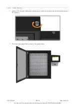
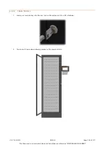
Page 145: ...ntrolled when printed unless over stamped CONTROLLED DOCUMENT 18 2 MANUALLY OPENING THE DOOR 18 2 1 TRAKA TOUCH V 1 Use a master key to open the control panel and lean it forward 2 Manually open the c...

Page 146: ...er stamped CONTROLLED DOCUMENT 18 2 2 TRAKA TOUCH M 1 To open the control panel you must insert the Master Key into the cam lock directly above the LCD and turn 90 clock wise 2 The control panel can n...

Page 147: ...s Document is uncontrolled when printed unless over stamped CONTROLLED DOCUMENT 3 To release the door you will need to locate the lock mechanism and lift the lock catch up 4 The door will pop open all...

Page 148: ...when printed unless over stamped CONTROLLED DOCUMENT 18 2 3 TRAKA TOUCH S 1 Located on the top of the cabinet is an override cam lock Insert your override key into the cam lock and turn 90 clockwise...

Page 149: ...cument is uncontrolled when printed unless over stamped CONTROLLED DOCUMENT 18 2 4 TRAKA TOUCH L 1 Insert your override key into the cam lock on the system and turn 90 clockwise 2 The door will now re...

Page 150: ...RSS section 1 Identify yourself to the Traka System by entering your Keypad ID or swiping your Card NOTE The user must be an administrator and have access to all the iFobs in the system 2 Select the I...

Page 151: ...if you wish to setup all items click the Yes button 10 A message will appear asking you whether you wish to replace the item you removed with the new item click the Yes button 11 The item list will no...

Page 152: ...tration menu From there click the Exit button again to return to the login screen 13 Identify yourself once again at the Traka System by entering your Keypad ID or swiping your Card 14 Select the I Kn...

Page 153: ...The key for the override switch will be different than the ones used for accessing the cabinet or the pod and should be stored in a secure location with strict access restrictions 18 4 1 ACCESSING TH...

Page 154: ...and turn the key through 90 then leave the key in that position 2 Press and hold the iFob release button on the desired iFob 3 Remove the iFob from the system then release the button 4 Repeat this pro...

Page 155: ...ncontrolled when printed unless over stamped CONTROLLED DOCUMENT 18 5 SERIAL NUMBER RATING PLATE LOCATION 18 5 1 TRAKA TOUCH V 1 Use a master key to open the control panel and lean it forward 2 The Ra...

Page 156: ...nless over stamped CONTROLLED DOCUMENT 18 5 2 TRAKA TOUCH M 1 Insert the Master key into the CAM Lock on the Control Panel 2 Turn the key 90 clockwise 3 The Control Panel will now lean forward on the...

Page 157: ...ver stamped CONTROLLED DOCUMENT 18 5 3 TRAKA TOUCH S TRAKA TOUCH L 1 Insert the Master key into the CAM Lock on the Control Panel 2 Turn the key 90 clockwise 3 The Control Panel will now lean forward...

Page 158: ...V9 7 01 05 20 UD0011 Page 158 of 177 This Document is uncontrolled when printed unless over stamped CONTROLLED DOCUMENT 18 6 TRAKA TOUCH PCB 18 6 1 IMX28 PCB...

Page 159: ...2 LCD Data Cable connections Along with the standard 7 connector used on the previous Control Board there is now a 5 connector for use with a 5 LCD display This Control Board is required when upgradin...

Page 160: ...15V Reader Connections Below is a closer look at the reader connections The Reader 1 Connector supports Wiegand and Clock Data card readers and shares the same pin out as the original Traka Touch and...

Page 161: ...r any reason you need to connect disconnect the battery please see the battery location and connection details below WARNING All Traka Systems have two power sources Mains and Battery Before installin...

Page 162: ...18 7 2 TRAKA TOUCH M BATTERY LOCATION 1 Insert the Master key into the CAM Lock on the Control Panel 2 Turn the key 90 clockwise and the Control Panel will lean forward on the restraining cable 3 You...

Page 163: ...ON 1 Located on the top of the cabinet is an override cam lock Insert your override key into the cam lock and turn 90 degrees clockwise 2 The door will now release allowing access to the receptor stri...

Page 164: ...olled when printed unless over stamped CONTROLLED DOCUMENT NOTE Please ensure none of the cables get caught trapped or tugged as you are opening the strip frame 5 Slotted in the bottom of the cabinet...

Page 165: ...code below 1 Insert the master key into the CAM lock on the side of the system 2 Turn the key 90 clockwise to open the door 3 The door will now open granting you access to the strips and cover panels...

Page 166: ...is Document is uncontrolled when printed unless over stamped CONTROLLED DOCUMENT 8 The battery is located at the bottom of the system and is held in place with a support bracket You will need a 7mm nu...

Page 167: ...E Depending on your system type the battery may differ slightly from the image below However the connection details remain the same For Battery disconnection carefully disconnect the spade connectors...

Page 168: ...t the Application diagnostic followed by Export App Log File to USB 2 You will be asked if you want to export the Current database The door will pop open and you must now insert a USB memory stick 3 Y...

Page 169: ...let In the case of a battery being fitted there are two power sources to disconnect before any service or maintenance work is carried out NOTE To safely power down and prevent the risk of data loss th...

Page 170: ...ct Traka distributor for technical support navigate to the Help section at the main screen and provide the following details Support Code Cabinet Serial Number App Version SQL CE DB Version CB FW Vers...

Page 171: ...posed Regulation on Privacy and Electronic Communications and references to Data Processor Data Subjects Personal Data Process Processed Processing Processor and Supervisory Authority have the meaning...

Page 172: ...party receiving the Hardware reads and agrees to accept the terms and conditions of this EULA 4 3 The Customer agrees not to modify disassemble reverse engineer derive the source code of decrypt crea...

Page 173: ...or 7 1 2 100 000 or 100 of the price paid for the Hardware whichever is lower 7 2 Subject to Clause 7 3 the Company accepts no liability for any 7 2 1 loss of business loss of revenue loss of profits...

Page 174: ...e of posting 13 Assignment Except as expressly set out in this EULA or as permitted by law the Customer will not be permitted to assign transfer charge hold on trust for any person or deal in any othe...

Page 175: ...obligations and exercising its rights under this EULA and as otherwise agreed by the parties from time to time 17 6 The Company 17 6 1 may appoint Authorised Sub Processors in connection with the perf...

Page 176: ...ement Personal Data 17 8 6 to the extent required by Data Protection Laws notify and provide reasonable assistance to the Customer on receiving any 17 8 6 1 complaint by a Data Subject in respect of t...

Page 177: ...ULA and the parties shall have no remedy in respect of any such statement or representation which is not set out in this EULA 18 2 Unless otherwise specified in the Commercial Terms if the Customer al...

Reviews: