background image

4

P/N YRL-EMICL-256-KFTSINSTL-FUL Rev A

1

Preparing Door


(if necessary)

!

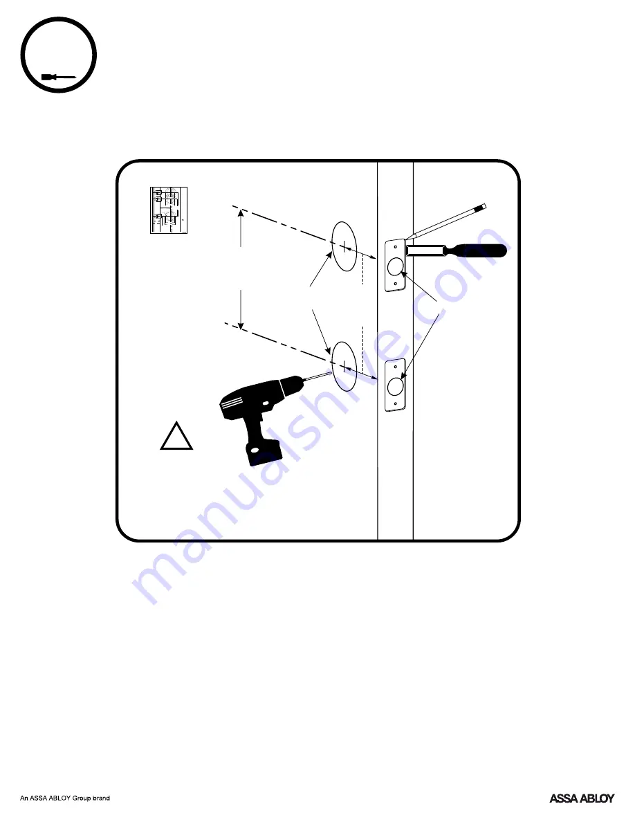
Drill holes 1/2 way thru 

door then complete 

from other side to 

prevent splitting.

Ø2-1/8"

2-3/8"

or

2-3/4"

Ø1"

4"

or

5.5"

Template

Door Thickness

FOLD HERE

Door Edge

Recommended Centerline 

36" (91 cm) From Floor.

Backset

5/32"

(3.96mm)

Caution:

 Copy machines 

may change the size of the 

template and make it 

inaccurate.

263006837 (01-16)

1" (25mm)

1" (25mm)

2-1/8" (54mm)

2-1/8" (54mm)

2-3/4" (70mm)

2-3/8" (60mm)

4" (101mm)

5-1/2" (139.7mm)

1" (25mm)

2-1/8" (54mm)

"Backset" is the distance 

from the door edge to the 

center of the mounting 

hole for the lever.

1-3/8"

(35mm)

1-3/4"

(45mm)

Caution:

 Although a door 

can be prepared by an 

untrained person, Yale 

recommends that 

measurements and drilling 

be done by a skilled 

carpenter or locksmith.

Yale® is a registered trademark of Yale

Security Inc., an ASSA ABLOY Group 

company. Copyright © 2016, Yale 

Security Inc., an ASSA ABLOY Group 

company. 

All rights reserved. Reproduction in 

whole or in part without the express 

written permission of Yale Security Inc. 

is prohibited.

www.yalelocks.com

1-800-438-1951

Interconnected

Lockset

An ASSA ABLOY Group brand

2-3/8" (60mm)

Summary of Contents for Yale Assure Lock YRC256-ZW3

Page 1: ...e specifications to ensure compliance with all codes and ratings Before you begin for step by step installation instructions to register your product DOWNLOAD THE BILT APP 4 Shown 5 5 Available Inside of Door Outside of Door Yale Assure Lock Installation and Programming Instructions YRC256 Interconnected Key Free Touchscreen Smart Module Optional ...

Page 2: ...70mm 2 3 8 60mm 4 101mm 5 1 2 139 7mm 1 25mm 2 1 8 54mm Backset is the distance from the door edge to the center of the mounting hole for the lever 1 3 8 35mm 1 3 4 45mm Caution Although a door can be prepared by an untrained person Y ale recommends that measurements and drilling be done by a skilled carpenter or locksmith Yale is a registered trademark of Y ale Security Inc an ASSA ABLOY Group co...

Page 3: ...t is the distance from the door edge to the center of the mounting hole for the lever 1 3 8 35mm 1 3 4 45mm Caution Although a door can be prepared by an untrained person Y ale recommends that measurements and drilling be done by a skilled carpenter or locksmith Yale is a registered trademark of Yale Security Inc an ASSA ABLOY Group company Copyright 2016 Yale Security Inc an ASSA ABLOY Group comp...

Page 4: ...1 2 139 7mm 1 25mm 2 1 8 54mm Backset is the distance from the door edge to the center of the mounting hole for the lever 1 3 8 35mm 1 3 4 45mm Caution Although a door can be prepared by an untrained person Y ale recommends that measurements and drilling be done by a skilled carpenter or locksmith Yale is a registered trademark of Yale Security Inc an ASSA ABLOY Group company Copyright 2016 Yale S...

Page 5: ...5 P N YRL EMICL 256 KFTSINSTL FUL Rev A 2 Installing Strike Plates Door Frame Inside of Door Frame 1 Dia x 1 Deep 1 Dia x 1 2 Deep Frame 7 16 8 32 x 1 UNCWS x4 ...

Page 6: ...Right Hand RH Hinges Right Open Inward Right Hand Reverse RHR Hinges Right Open Outward The hand of a door is determined from the secure side of the door The term secure means the side from which you initially unlock and enter Determining Handing 6 P N YRL EMICL 256 KFTSINSTL FUL Rev A ...

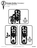
Page 7: ...ICL 256 KFTSINSTL FUL Rev A 3 Changing Handing if necessary 4 24 x 1 4 PPHMS 4 Left Hand to 4 Right Hand Shown x2 3 DO NOT TAMPER WITH OR LOOSEN E CLIP AND ITS ASSEMBLY DO NOT LOOSEN THESE 6 SCREWS OR REMOVE COVER ...

Page 8: ...Changing Handing if necessary continued 3 8 P N YRL EMICL 256 KFTSINSTL FUL Rev A ...

Page 9: ...and For 5 5 For 4 4 Right Hand For 5 5 For 4 After handing is changed check that lever and thumbturn rotate freely Test Lever and Thumbturn Confirm RH is visible thru RH hole as shown for right hand installation Confirm LH is visible thru LH hole as shown for left hand installation ...

Page 10: ...10 P N YRL EMICL 256 KFTSINSTL FUL Rev A 4 Installing Fire Cup Inside of Door Fire Cup and a UL marked Latchbolt must be used to qualify for UL listing ...

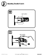
Page 11: ...11 P N YRL EMICL 256 KFTSINSTL FUL Rev A 5 Adjusting Deadbolt Latch O optional default UP 2 3 8 position UP 2 3 4 position Press Pull ...

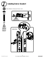
Page 12: ...t based on backset 2 3 8 or 2 3 4 Inside of Door Bolt must be in retracted unlocked position before installing Ensure arrow stamped on deadbolt is UP UP Spacer collar must be used for 1 edge bore Collar can be removed for 3 4 edge bore Edge bore can be 3 4 or 1 only Curved edge of latchbolt faces direction door closes ...

Page 13: ...Exterior Deadbolt UP Inside of Door Confirm bolt is retracted unlocked Choose through bolt appropriate for your door thickness M6x44 PPHMS for standard door thickness shown x2 13 P N YRL EMICL 256 KFTSINSTL FUL Rev A ...

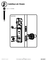
Page 14: ...14 P N YRL EMICL 256 KFTSINSTL FUL Rev A 8 Installing Lock Chassis 10 32 x 1 1 2 PPHMS Inside of Door x2 UP ...

Page 15: ... YRL EMICL 256 KFTSINSTL FUL Rev A 9 Securing Back Plate to Door Two 6 32 x 1 2 POHMS screws must be used to qualify for UL listing Drill two pilot holes Ø1 8 x 1 2 deep Inside of Door UP x2 6 32 x 1 2 POHMS ...

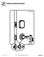
Page 16: ...16 P N YRL EMICL 256 KFTSINSTL FUL Rev A Testing Latchbolt Operation Outside of Door ...

Page 17: ...17 P N YRL EMICL 256 KFTSINSTL FUL Rev A 10 Attaching the Cable Assembly Test that cables are securely connected UP Inside of Door Avoid interference with movement of lock when routing cable ...

Page 18: ...18 P N YRL EMICL 256 KFTSINSTL FUL Rev A 11 Installing Interior Lock Turn thumbturn to adjust tailpiece orientation UP Inside of Door ...

Page 19: ...19 P N YRL EMICL 256 KFTSINSTL FUL Rev A 11 Installing Interior Lock continued 10 32 x 5 8 POHMS x1 6 32 x 1 PPHMS x2 Inside of Door DO NOT LOOSEN THIS SCREW ...

Page 20: ...20 P N YRL EMICL 256 KFTSINSTL FUL Rev A Pull lever to ensure it is secure 12 SNAP Installing Interior Lever Inside of Door Inside of Door ...

Page 21: ...21 P N YRL EMICL 256 KFTSINSTL FUL Rev A Testing Final Latchbolt Operation Outside of Door Inside of Door ...

Page 22: ...Final Deadbolt Operation If resistance re check installation and confirm mounting screws have not been over tightened Confirm deadbolt operates smoothly with no resistance 22 P N YRL EMICL 256 KFTSINSTL FUL Rev A ...

Page 23: ...13 Installing Optional Smart Module DO NOT install Smart Module with batteries in unit Damage may occur 23 P N YRL EMICL 256 KFTSINSTL FUL Rev A ...

Page 24: ...Bolt must be in retracted unlocked position before installing batteries Tighten screw to replace cover Welcome to Yale Real Living 14 Installing Batteries Cover 24 P N YRL EMICL 256 KFTSINSTL FUL Rev A ...

Page 25: ...ouchscreen YRC256 Continue with the Programming Instructions to customize your product AFTER installing batteries and cover or AFTER a factory reset activate touchscreen and create Master PIN code Lock will then automatically determine handing See 1 of Programming Instructions for how to set master code Handing the Lock ...

Page 26: ...rly see Step 10 e Verify bolt is installed with correct side up see Step 6 Keypad numerics are scrolling Remove interior lock and check to ensure that the wire harness is routed properly see Step 10 Door is binding a Check that door and frame are properly aligned and door is free swinging b Check hinges They should not be loose or have excessive wear on knuckles Bolt will not extend and lock jam a...

Page 27: ...ng Max User Codes 250 with Z Wave Plus or Zigbee network module Max User Codes 25 without network module or with iM1 network module Max User Codes 12 with Bluetooth OR Interior Escutcheon Speaker Low Battery Indicator Lockout Mode Failsafe 9 volt Battery Connection Use Alkaline battery P Key Return to Previous Exterior Escutcheon Privacy Button ...

Page 28: ...ontinue Enter a 4 to 8 digit PIN code followed by the gear key Registered Creating a Master PIN Code must be performed upon installation or after resetting the lock to factory default Programming and use of lock is not possible until this step has been successfully completed 28 P N YRL EMICL 256 KFTSINSTL FUL Rev A ...

Page 29: ... PIN code Press code flashes Press Menu Mode enter number press the gear key to continue 2 Creating User PIN Codes Master PIN code must be created first Max user codes 250 with Z Wave or Zigbee network module Max user codes 25 without network module or with iM1 network module Max user codes 12 with Bluetooth 29 P N YRL EMICL 256 KFTSINSTL FUL Rev A ...

Page 30: ... PIN Code Press 3 Unlocking Door with PIN Code PIN Code Management With Network Module Up to 250 Users Duplicate if necessary User Name PIN Code Master User User User User User User Code Chart User User User User Type User User User User User User ...

Page 31: ...or lock onto the door Upon reset Master PIN Code creation is the only option available and must be performed prior to any other programming of the lock The Master PIN code must be registered prior to any other programming of the lock Factory Setting Registration required Disabled Disabled Off Enabled Enabled Low 5 Times 60 Seconds Settings Master PIN Code Automatic Re lock Inside Indicator Light O...

Page 32: ...ackup power option Wake up the lock and enter your pin code to unlock the door Master PIN Code The Master PIN code is used for programming and for feature settings It must be created prior to programming the lock The Master code will also operate unlock lock the lock One Touch Locking When the latch is retracted activating the keypad will extend the latch during Automatic Re lock duration or when ...

Page 33: ...ommands The Master PIN code must be registered prior to any other programming of the lock Note After Master PIN code is entered lock will automatically hand itself For best results lock should be installed on door during this process If this process was done and lock was not installed on door review the Re Handing instructions listed in Hardware Troubleshooting Master PIN Code Setting M User Codes...

Page 34: ...34 P N YRL EMICL 256 KFTSINSTL FUL Rev A Programming Troubleshooting Check or gear Symptom Suggested Action ...

Page 35: ...s Class A digital apparatus meets all requirements of the Canadian Interference Causing Ÿ Connect the equipment into an outlet on a circuit different from that to which the receiver is connected Ÿ Reorient or relocate the receiving antenna Equipment Regulations Cet appareillage numérique de la classe A répond à toutes les exigences de l interférence canadienne causant des règlements d équipement F...

Page 36: ...ollow the instructions included with it Removing a Yale Z Wave Plus Smart Module from your Assure Lock Z Wave System 1 Install the Yale Smart Module into the slot above the battery compartment IMPORTANT The batteries must be removed before removing the Yale Smart Module Remove battery cover Remove batteries Insert or remove Yale Smart Module Reinstall batteries Reinstall battery cover 2 Open the Z...

Page 37: ...e le risque d interférence aux autres utilisateurs le type d antenne et son gain doivent être choisies de façon que la puissance isotrope rayonnée équivalente PIRE ne dépasse pas ce qui est nécessaire pour une communication réussie Section 7 1 3 of RSS GEN This Device complies with Industry Canada License exempt RSS standard s Operation is subject to the following two conditions 1 this device may ...

Page 38: ... Yale Locks Z Wave Plus v2 System Integrators Guide for Marketing Yale Assure Electronic Deadbolts YRD216 ZW3 YRD226 ZW3 YRD256 ZW3 YRC216 ZW3 YRC226 ZW3 YRC256 ZW3 Document Revision 1 4 October 20 2020 ...

Page 39: ...2 Contents Yale Z Wave Plus Product Info 3 Supported Command Classes 3 Association Table 4 Notifications Table 4 Configurable Parameters 9 ...

Page 40: ...utton Deadbolt o 0x8002 for YRD226 ZW3 YRC226 ZW3 YRD256 ZW3 YRC256 ZW3 Touch Screen Deadbolt Supported Command Classes Command Class Z Wave Plus Info Command Class Manufacturer Specific Command Class Security Command Class Security 2 Command Class Device Reset Locally Command Class Power Level Command Class Version Command Class Battery Command Class Door Lock Command Class Door Lock Logging Comm...

Page 41: ...cation_Report Command_Class_Door_Lock V4 o Door_Lock_Operation_Report o Door_Lock_Configuration_Report Command_Class_Device_Reset_Locally V1 o Device_Reset_Locally_Notification Command_Class_Indicator V3 o Indicator_Report Command_Class_User_Code V2 o User Code Report Command_Class_Clock V1 o Clock_Report Notifications Table Table 2 Notifications Table Alarm Reports Alarm type Alarm Level Descript...

Page 42: ...01 Manual Unlock 0x16 0x01 By key cylinder or inside thumb turn 0x06 0x02 RF Operate Lock 0x18 0x01 by RF module 0x06 0x03 RF Operate Unlock 0x19 0x01 by RF module 0x06 0X04 Auto Lock Operate Locked 0x1B 0x01 Auto re lock cycle complete locked 0x06 0x09 User deleted 0x21 0x 01 max users User was deleted Alarm level user slot number 0x06 0X0D single 0X0C all Door State 0x23 0x00 Door is open 0x06 0...

Page 43: ...ified user ID 0x06 0xFE Master Code changed 0x70 0x00 Master code was changed at keypad 0x06 0x12 0xFB Master code was changed over RF 0x06 0x0E User added 0x 01 max users User added Alarm level user slot number 0x06 0X0E Duplicate Pin code error 0x71 0x 01 max users Where Alarm level represents user slot number Alarm generated in response to add user RF cmd This alarm is not generated when attemp...

Page 44: ...arm 0xA1 0x01 keypad attempts exceed code entry limit 0x06 0X10 0x02 front escutcheon removed from main 0x06 0xFE Battery is fully charged 0x80 0x05 After a low battery alert was observed the lock was powered down and powered back up with full battery 0x08 0x0D Door Lock needs Time set 0x82 0x00 Power to the lock was restored and the locks RTC was cleared The controller should set the time to ensu...

Page 45: ...supports a 3rd low battery alarm too low to operate This alarm is sent out as a Battery Report with value 0xFF through the Battery Command Class This is the last low battery alarm level before the product stops functioning ...

Page 46: ...feature to enable or disable 45 3 Relock time Signed Integer 1 byte 0x0A 10 seconds 0xB4 180 seconds 0x1E 30 seconds Adjust the time your lock will auto relock 43 4 Wrong Code Entry Limit Signed Integer 1 byte 0x03 0x0A 0x05 Adjust the limit for wrong code entries allowed by your lock 61 5 Language Signed Integer 1 byte 0x01 English 0x03 French 0x01 English Set the language to English 1 Spanish 2 ...

Page 47: ...xFF Enable Set One Touch Locking feature to enable or disable 51 12 Privacy Button Unsigned Integer 1 byte 0x00 Disable 0xFF Enable 0x00 Disable Set Privacy Button feature to enable or disable 48 13 Lock Status LED Unsigned Integer 1 byte 0x00 Disable 0xFF Enable 0x00 Disable Set Lock Status LED feature to enable or disable 57 15 Reset To Factory Defaults Unsigned Integer 1 byte 0x01 0x01 N A Lock...

Reviews: