An ASSA ABLOY Group brand
80-9086-0050-010 (10-12)
8
Steps
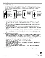
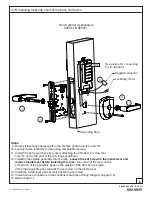
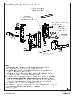
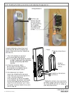
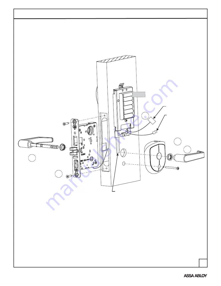
9. Route all lockbody harnesses thru the mortise pocket and thru hole “E”.
10. Loosely fasten lockbody to door using combination screws.
11. Install I/S short escutcheon by loosely attaching the #10-24 X 2 screw thru
hole “D” and to the post of the O/S long escutcheon.
12. Installing the spindle assembly thru the lock.
Loosen the set screw on the inside lever and
remove inside lever before installing thru lock.
Be sure that the lever on the
pinned end of the assembly goes on the outside of the door and the ramp
of the inside spindle goes towards the set screw on the inside lever.
13. Install the inside lever and securely tighten the set screw.
14. Install harness connectors to the controller board (see Wiring Diagram on page 12).
15. Skip to page 11.
"
REMOVE
BEFORE
USE
Keypad connector
Lockbody motor
See picture for
to circuit board
connecting
REMOVE
BEFORE
USE
IV-B Installing lockbody, short escutcheon and levers
Non-Cylinder Applications
8850FL & 8852FL
D
A
11
9
12
13
10
E
Grounding Strip


