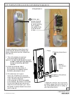
An ASSA ABLOY Group brand
80-9086-0050-010 (10-12)
9
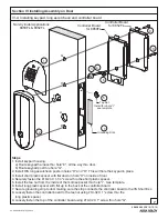
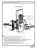
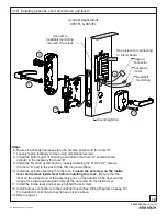
Steps
1.
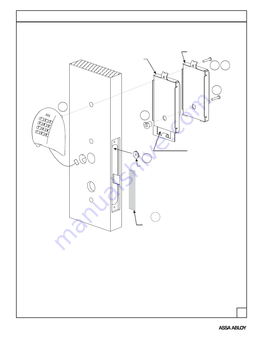
a) Route keypad harness thru hole “E”, all the way thru door
b) Route keypad post thru hole “G”.
2. Loosely fasten the #10-32 X 1 screw thru hole “G” and into the keypad post.
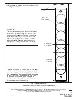
3. Install the tee nut from the inside of the mortise pocket thru hole “I”. See template.
4. Install the long plastic spacer (with flat any orientation) in the back of the controller board.
5. Secure grounding strip to door making sure the strip connects the controller board to the I/S Short Esc.
6. Loosely fasten the controller board to the tee nut using #10-32 X 1 screw thru the long
plastic spacer.
7. Loosely fasten the #10-32 X 1 screw thru hole “G” and into the keypad post.
Install keypad housing:
"
"
"
IV-C Installing keypad and controller board
Cylinder Applications
8851FL & 8853FL
Controller Board
for 8853FL
Controller Board
for 8851FL
Route keypad
wire/connector
through controller
Board housing
4
1
2
3
6
Install thru hole “I”
see template
G
H
E
A
D
7
B
5
Grounding Strip


