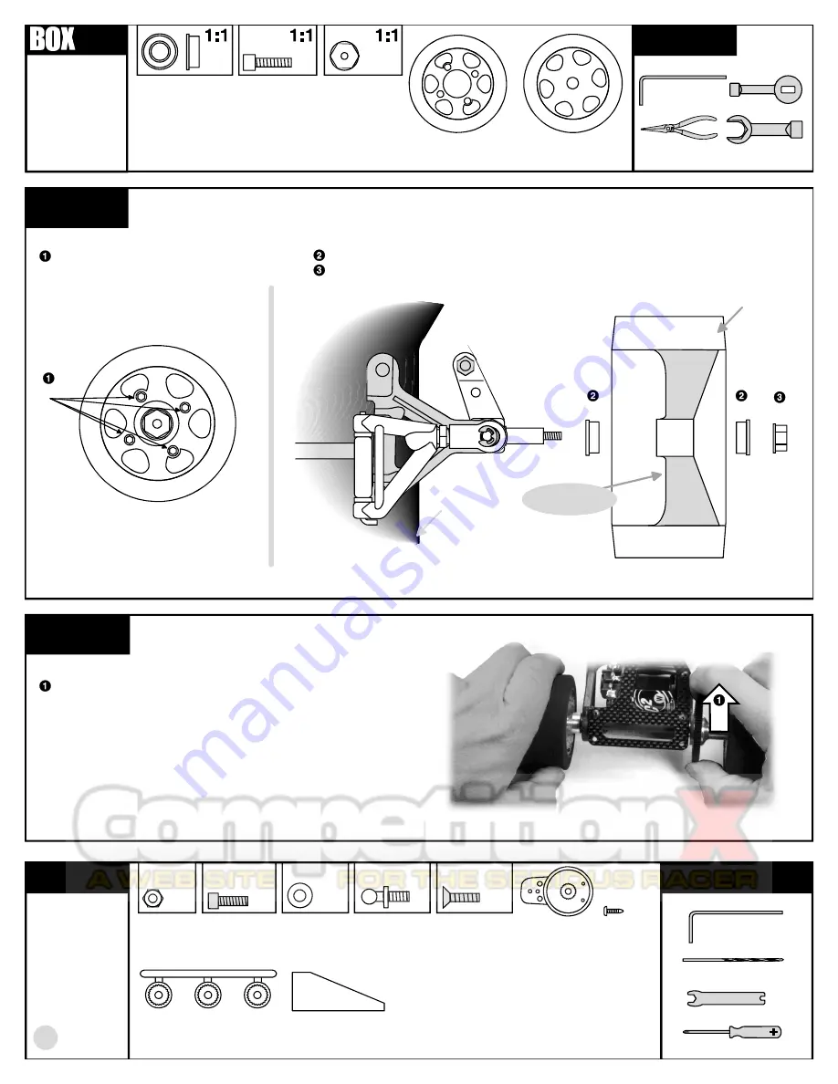
REMOVE THESE
PARTS FOR:
8018: steps 1-2
TOOLS USED
step 1
LEFT SIDE
6222, qty 2
4-40/5-40
nylon locknut
6902
6902
6222
DIFFERENTIAL ADJUSTMENT
While holding both rear wheels with your hands as shown, use
your right thumb and index finger to try and rotate the spur
gear. The spur gear should be very difficult to rotate. If you can
rotate it easily, then tighten the #4185 11/32" nut at the end of
the axle,
a little at a time,
until the spur gear is difficult to
rotate.
step 2
12
MOUNTING REAR TIRES
Install both #8166 rear tires to the
hubs with four #6924 screws into
each wheel hub.
6902, qty 4
3/16 x 5/16
flanged ball bearing
chassis
8166
6924
MOUNTING FRONT TIRES
Put a #6902 flanged ball bearing into each side of the #8146 front wheels.
Slide the wheel on and secure it with a #6222 nut. Install the other wheel the same way.
6924, qty 8
4-40 x 3/8
#8166, qty 2
rear wheel/tire
#8146, qty 2
front wheel/tire
SIDE VIEW SHOWN
SIDE VIEW SHOWN
TOP VIEW SHOWN
TOP VIEW SHOWN
3/32"
BAG E
REMOVE THESE
PARTS FOR:
8018: steps 1-2
8435, qty 2
servo mounting block
TOOLS USED
4145, qty 4
4-40 x 5/16
blue aluminum
1:1
7337, qty 4
#4 washer
1:1
8445, qty 1
servo saver
8445, qty 1
servo saver
screw
8445, qty 1
servo saver
adapter
4448, qty 2
ball end
1:1
6934, qty 2
4-40 x 3/8
blue aluminum
1:1
4449, qty 2
4-40 locknut
1:1
1/16", 3/32"
8146
front tire
#43 (3/23") drill
ribs face
toward chassis


