-
+BATTERY-
-
15
step 5
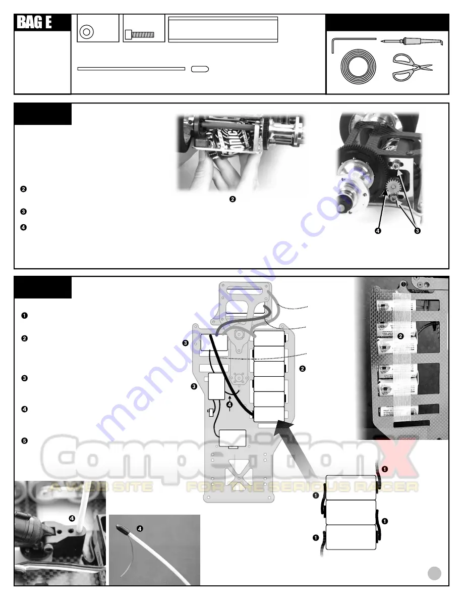
PINION GEAR INSTALLATION
Slide the pinion gear onto the shaft so that the
gear is 1/16" away from the motor can. Tighten
the set screw to hold it in place. Teeth side
should be farthest from can.
MOTOR INSTALLATION
Insert the motor into the rear pod assembly as
shown, the pinion gear coming through the
right side motor bulkhead.
Tighten the motor to the bulkhead with two
#6515 screws and two #7337 gold washers.
Set the gear mesh so that there is very little
play between the spur and pinion gear.
Note:
If the gear mesh is too tight, you can lose
significant power.
REMOVE THESE
PARTS FOR:
8018: steps 5-6
TOOLS USED
7337, qty 2
washer
gold, steel
1:1
MOTOR AND PINION GEAR ARE NOT INCLUDED IN KIT
6515, qty 2
3mm x 10mm
gold
1:1
step 6
STEERING
SERVO
-
+BATTERY-
-
+BATTERY-
-
+BATTERY-
SPEED
CONTROL
MOTOR
+
+
__
ELECTRICAL INSTALLATION
Solder your single cell batteries together
with battery braid or battery bars. Solder
plus (+) to minus (-).
Hold the batteries to the chassis with
strapping tape. Wrap the tape over the
batteries, through the chassis slot,
underneath the chassis, and up again
through another slot, several times.
Cut the #6726 servo tape to fit the
bottom of the speed control and receiver.
Peel the backing from the servo tape and
place them where shown in the drawing.
Insert the #3716 antenna into the
antenna mount. Slide your receiver
antenna wire through the antenna and
secure the wire with the antenna cap.
Now connect the electronic speed control
and steering servo to your receiver
according to your radio or ESC
instructions,
then connect the motor to
the ESC and battery.
ELECTRICAL ITEMS ARE NOT INCLUDED IN KIT
3716, qty 1
antenna
3716, qty 1
antenna cap
strapping tape
R
E
C
E
IV
E
R
6726, qty 1
servo tape strip
antenna
wire
1
RED WIRE
BLUE WIRE
BLACK WIRE
3/32"
TOP VIEW
BOTTOM VIEW


