background image

:: 

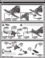
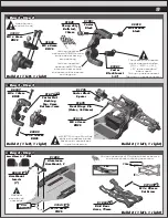
:: Bag 3 - Step 1

Bag 3 - Step 1

:: 

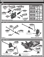
:: Bag 2 - Step 8

Bag 2 - Step 8

8

:: 

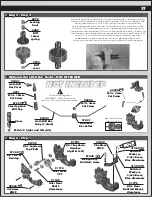
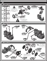
:: Bag 2 -

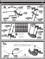
Bag 2 - Step 7

Step 7

!

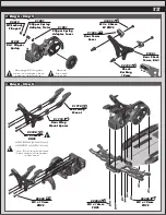
#91978 - Front Wing Mount is used as a tuning option to 

increase front end stabillity by adding a front wing (included).  

If you do not use #919778, use #25202 

M3x10mm FHCS instead of #89208 M3x14mm FHCS.

25215

M3 Locknut, 

black

71144

Steering 

Block Arm, 

+1mm

91047

Heavy-duty 

Ballstud, 

6mm

91670

Front Hinge Pin 

(Inner, 3x34mm)

25225

M3 x 3mm 

Set Screw

x2

x2

x2

x2

25204

M3 x 16mm 

FHCS

91685

Front 

Bumper

x2

x2

!

25188

M3 x 20mm 

BHCS

91815

Shock 

Bushing,

10mm

91880

Front Shock 

Tower, B6.3, 

Gull-Wing

91885

Front Shock 

Tower Cover

91885

Front Shock 

Tower Nut

x2

x2

x2

x2

31520

M2.5 x 6mm 

BHCS

x2

x2

3

32211

25202

M3 x 10mm 

FHCS

89208

M3 x 14mm 

FHCS

91978

Wing Mount, 

Front

x2

x2

x2

x2

Build 2 (1 left, 1 right)

x2

x2

31531

M3 x 6mm 

BHCS

91560

5 x 10 x 4

Bearing

91682

Front Axle

91901

Steering 

Block

(4mm)

#1596

thread lock

There are two sets of steering 

blocks included with your kit, a 3mm 

and a 4mm.  The 4mm steering 

blocks are used for the kit setup.

!

4L - 1

Summary of Contents for 90035

Page 1: ...AssociatedElectrics com ...

Page 2: ...ngle change New chassis side rails with 3 optional fan mount locations to choose from New caged thrust bearing for ball differential New cab forward design RC10B6 4 bodyshell offered in standard kit and lightweight optional thickness Front wing mount and front wing included Clear body and clear wing included 5mm aluminum clamping rear wheel hexes Cyanoacrylate glue CA 1597 Thread locking compound ...

Page 3: ... 3 32 Ceramic Diff Balls 6584 Thrust Washer 91990 Caged Thrust Washer 91990 Diff Balls M3 Plain Nut 91477 M3 Alum Locknut Blue 31550 M3 Locknut Black 25215 M3 Locknut w Flange 25612 FT 3mm Locknuts Blue 25392 M4 Nuts Serrated Steel Silver 91826 FT Alum Locknut Blue 25391 Serrated Steel Black 91738 Serrated Steel LP Black 91150 Nuts lock plain Ballstuds Silver 5mm long 31283 Silver 8mm long 31284 H...

Page 4: ...es 16 18 Bag 9 Shocks 19 23 Bag 10 Battery Strap Body and Wheels 24 25 Tuning Tips 26 Back Cover There is a 1 1 hardware foldout page in the front of the manual To check the size of a part line up your hardware with the correct drawing until you find the exact size Each part in the foldout has a number assigned to it for ordering replacement parts Associated Electrics Inc 21062 Bake Parkway Lake F...

Page 5: ... Bearing 91973 Steering Rack x4 x4 x4 x4 x2 x2 x2 x2 91048 Heavy duty Ballstud 8mm 31382 FT Ballstud Washer Aluminum 1mm x2 x2 x2 x2 91049 Heavy duty Ballstud 10mm 31382 FT Ballstud Washer Aluminum 1mm 91971 Front Ball Stud Mount Do not overtighten NOT INCLUDED NOT INCLUDED NOT INCLUDED NOT INCLUDED NOT INCLUDED NOT INCLUDED NOT INCLUDED NOT INCLUDED NOT INCLUDED NOT INCLUDED NOT INCLUDED NOT INCL...

Page 6: ...mm and 16mm are in the screw bag Use the shorter of the two screws x2 x2 89208 M3 x 14mm FHCS 91979 Bulkhead use 0 91967 B6 4 Chassis 91728 Servo Horn Ring 31284 8mm Ball Stud Long 91728 Servo Horn Servo not included 31531 M3 x 6mm BHCS x4 x4 91749 M2 x 3mm FHCS 91976 B6 4 FT Alum Chassis Weight 13g 91988 Battery Foam B6 4 x4 x4 x5 x5 25202 M3 x 10mm FHCS 91969 Side Rails L R 25201 M3 x 8mm FHCS 9...

Page 7: ...t required for most servos 41089 M3 x 6mm LP SHCS x4 x4 1596 thread lock 25202 M3 x 10mm FHCS x2 x2 1596 thread lock 91971 Top Plate B6 4 25187 M3 x 14mm BHCS x2 x2 The front hinge pin brace has a sharp edged side and a rounded edge side Mount the sharp edge side towards the bulkhead 25211 M3 x 10mm BHCS x2 x2 31510 M2 x 4mm BHCS 91673 Front Arms Gull Wing B6 91657 Front Hinge Pin Brace B6 x2 x2 ...

Page 8: ...mm FHCS 91685 Front Bumper x2 x2 25188 M3 x 20mm BHCS 91815 Shock Bushing 10mm 91880 Front Shock Tower B6 3 Gull Wing 91885 Front Shock Tower Cover 91885 Front Shock Tower Nut x2 x2 x2 x2 31520 M2 5 x 6mm BHCS x2 x2 3 32 21 1 25202 M3 x 10mm FHCS 89208 M3 x 14mm FHCS 91978 Wing Mount Front x2 x2 x2 x2 Build 2 1 left 1 right x2 x2 31531 M3 x 6mm BHCS 91560 5 x 10 x 4 Bearing 91682 Front Axle 91901 ...

Page 9: ...1531 M3 x 6mm BHCS 31532 M3 x 8mm BHCS Build 2 1 left 1 right Build 2 1 left 1 right Build 2 1 left 1 right 91670 Hinge Pin will be tight in the caster blocks but should rotate freely in the front arms Use shorter screw in front 25187 M3 x 14mm BHCS 89202 M3 x 12mm BHCS 91676 Caster Hat Bushing Top 2mm Bottom 1mm x2 x2 31510 M2 x 4mm BHCS 91776 Caster Block Spacer 91670 Front Hinge Pin Outer 3x26m...

Page 10: ... your wrench for better control The 91882 C and 91883 D aluminum arm mounts allow for a large amount of setup combinations when using the 92014 0 5 and 1 arm mount inserts For a complete list of pill setup combinations please visit our website by using the link below http bit ly B6PillChart Anti Squat Toe In 3 Kit Setup 2 Kit Setup Arm Mount C 1 Out Out Out Arm Mount D 1 Out Down Out Down Out Down...

Page 11: ... driven the car once re check the diff setting 6575 Diff cover 6575 Locking T nut 6582 Diff thrust spring 91791 B6 1 Laydown Gearbox right left 91560 5 x 10 x 4 Bearing 89203 3x16mm BHCS 31472 2 5x8mm FHCS 91716 Idler Gear 39T 91799 B6 1 Laydown Top Shaft 91132 Idler Gear Shaft Aluminum x4 x4 x2 x2 91048 Heavy duty Ballstud 8mm x2 x2 x2 x2 x2 x2 91775 B6 1 Rear Ballstud Mount Aluminum 31383 Ballst...

Page 12: ...2 Laydown Motor Plate x3 x3 92295 Octalock Spur Gear 78T 48P 91799 B6 1 Top Shaft Screw and Pin x2 x2 92286 FT Octalock LCF Slipper Pad 19mm 91803 B6 1 Slipper Hub Inner 91804 B6 1 Slipper Hub Outer 92295 spur gear walls should point away from gear box There s also a 72T 48P spur gear 92293 included for stock motor use 6591 diff lube Add a drop of Diff Lube 6591 to the teeth of the diff gear idler...

Page 13: ...ipper Spring 25612 M3 Locknut Flanged 3 3 4 4 2 21 1 41095 M3 x 22mm LP SHCS 91885 Rear Tower Cover x2 x2 x2 x2 92159 Shock Bushing 10mm 91881 Rear Shock Tower B6 3 x2 x2 89202 M3 x 12mm BHCS x4 x4 25188 x4 M3x20mm 89202 x4 M3x12mm use 12mm length screws if rear wing mount spacer is removed 25188 M3 x 20mm BHCS x4 x4 x2 x2 x2 x2 91718 Rear Wing Mount 91718 Rear Wing Mount Spacer 25202 M3 x 10mm FH...

Page 14: ...k grease Note the location of the L and R on the rear hub 91563 10 x 15 x 4 Bearing 91567 5 x 12 x 4 Bearing 91859 B6 2 CVA Axle 2mm 91438 CVA Pin 91438 CVA Coupler 91860 CVA Bone 69mm Hinge Pin will be tight in the rear hub but should 92179 Rear Hub Spacer x2 x2 92188 Rear Hub Hinge Pin 25215 M3 Locknut Build x2 right and left side 89202 M3 x 12mm BHCS x2 x2 91047 Heavy duty Ballstud 6mm 92180 Re...

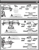
Page 15: ...tion Build x2 right and left side Front Camber Turnbuckle 22 50mm Orient the notch to the left throughout the car It indicates which end has the left hand threads 91722 Ball Cup 91722 Ball Cup 91722 Ball Cup 91722 Ball Cup 91723 Turnbuckle 3x48mm 91723 Turnbuckle 3x48mm 27 90mm Steering Turnbuckle Build x2 right and left side Orient the notch to the left throughout the car It indicates which end h...

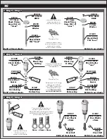
Page 16: ...Tip Coating the O rings with green slime 1105 helps seal reduce O ring swell Green slime not included in kit 91920 13x23mm Shock Bodies front 91922 13x27 5mm Shock Bodies rear 91996 13mm Shock Hat Bushing 91996 13mm Shock Hat Bushing 91996 13mm Shock Spacer 91996 13mm Shock Spacer 91493 X Ring 91493 X Ring 31327 VCS3 Shock Bottom Cap 31327 VCS3 Shock Bottom Cap 91996 13mm Shock Cap O Ring 91996 13...

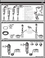
Page 17: ... a drop of oil in the cap and on cap threads 8 Install cap without bleed screw and tighten completely 9 Slowly compress shaft all the way to bleed excess silicone shock fluid out the hole in the cap use rag around shock to catch excess fluid 10 Install M2x4mm button head screw until snug while shaft is fully compressed 5422 31510 M2 x 4mm BHCS 91926 13mm Shock Cap Stroke Front 21mm Rear 27 5mm Str...

Page 18: ...1 Build x2 right and left side 25612 M3 Locknut w Flange Build x2 right and left side Use outside hole in front arm 25188 M3 x 20mm BHCS x2 x2 25612 M3 Locknut w Flange Make sure the flange on the shock pivot ball is towards the rear arm 3 3 4 4 2 2 B C A 1 1 ...

Page 19: ...mm FHCS 89203 M3 x 16mm BHCS 91978 Fan Mount 1 Fan mount options 1 Laydown gearbox 2 Layback gearbox 3 Endbell location 4 Plug no fan See page 25 for gear mesh setting instructions Motor not included Pinion Setscrew not included 31532 M3 x 8mm BHCS x2 x2 x2 x2 89218 3 x 8mm Washer 1 2 3 4 ...

Page 20: ...ke sure the battery strap shoulder screw is flush with the top of your battery pack R R F F 91731 Battery Strap B6 91730 Battery Strap Shoulder Screw x2 x2 ESC not included 6727 Servo Tape Antenna can be mounted on the right or left side of the chassis Receiver not included Transponder not included 25225 M3 x 3mm Set Screw 6338 Antenna Tube Cap 91158 M3 x 4mm BHCS x2 x2 ...

Page 21: ...ith M3x16mm BHCS Pro Tip Set the turnbuckle length based on battery position adjust the length as needed to mate with the gearbox OPTION Tune for more chassis flex 91885 Rod End 91885 Rod End 91723 Turnbuckle 3x48mm Varies with battery position 3F 29mm Battery Brace Turnbuckle 25612 M3 LockNut w Flange 25204 3 x 16mm FHCS 91819 Shock Pivot Ball x2 x2 1 1 2 2 3 3 4 4 5 5 Front Front 91729 Thumb Scr...

Page 22: ...used ONLY for shocks mounted on the rear of the arms Install hook and loop tape 91743 along the side braces in 2 spots One near the front and one in the middle Install the opposite side of the hook and loop tape inside the body Front of Vehicle 6 Mount under wing KIT 3 Mount on top of wing 0 Mount under wing Wing Mount 91718 Wing Button 91741 Wing B6 91718 Wing Mount 25202 M3 x 10mm FHCS x2 x2 x2 ...

Page 23: ...ng Mounting There are 2 body trimming options depending on what transmission you choose to run Cut Line A is for 3 endbell or 4 no fan Cut Line B is for running a fan 1 or 2 location Body Trimming for Length There are 2 body trimming options depending on what transmission you choose to run Cut the body on the top rear long for the B6 4 shorter for the B6 4D Build 2 1 left 1 right Build 2 1 left 1 ...

Page 24: ...ter and liquid detergent do not use any detergents with scents or added hand lotion ingredients Dry the body using a clean soft lint free cloth Use the supplied window masks to cover the windows from the INSIDE of the body RC cars get painted on the inside Using high quality masking tape apply tape to the inside of the body to create a design Spray use either rattle can or airbrush the paint on th...

Page 25: ...e directions the quickest and generate the most steering Layback is used for most indoor clay track conditions Caster Caster describes the angle of the caster block as it leans toward the rear of the vehicle Positive caster means the kingpin leans rearward at the top The kit includes three inserts to adjust caster angle at the caster block 0 2 5 and 5 The total caster angle is the sum of the kick ...

Page 26: ......
Reviews: