background image

15

:: Shock Maintenance - (cont.)

:: Shock Maintenance - (cont.)

:: Shock Maintenance - (cont.)

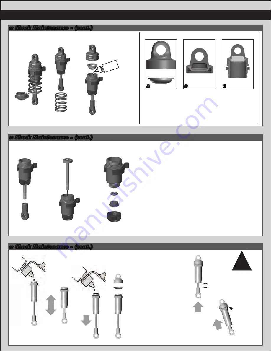
Shock Maintenance:

If you need to only refill your shocks with oil, follow the steps 

above only then move to the shock bleeding steps.

If your shocks leak from the bottom shock cap, follow all 

shock maintenance sections.

Replace the inner O-Ring in the bottom cap, then begin the 

shock oil filling and bleeding process.

Step 9-10

Stock Shock 

Fluid Setting:

Front: 35wt

Rear: 35wt

Step 6-8

Slow

Slow

Check for 

pressure

Step 5

Step 3-4

Step 1-2

Shock Bleeding Steps:

1. 

Pull shock shaft down.

2. 

Fill shock body 3/4 full with silicone 

shock fluid.

3. 

Slowly move the shock shaft up and 

down to remove air from under the 

piston.

4. 

Wait for bubbles to come to surface.

5. 

Fill shock body to top with silicone 

shock fluid.

6. 

Place a drop of oil in the cap and on 

cap threads.

7. 

Install cap and tighten completely.

8. 

Unscrew the cap 3/4 turns and tilt 

the shock at a slight angle.

9. 

Slowly compress shaft all the way to 

bleed excess silicone shock fluid and 

air.  You should see bubbles coming 

out from under the cap. (use rag 

around shock to catch excess fluid).

10.  With the shaft compressed, tighten 

the cap and re-check for pressure at 

the top of the stroke.  If there is still 

pressure, repeat steps 3-9.

Some residual 

shock fluid may 

appear from your 

first few runs 

around the shock 

cap as a result of 

bleeding.

!

Bladder Installation

As you install the shock cap with the bladder, it will force 

out any extra fluid.  If you install the cap with the shaft 

fully extended, you are running FULL REBOUND.This 

means the shaft will fully rebound when compressed.

To run less rebound, unthread the cap 1-2 turns and 

compress the shaft to the desired position and 

re-tighten the cap with the shaft compressed.

Start with no rebound.

A

B

C

35wt 

Shock fluid

Summary of Contents for Qualifier Series

Page 1: ...12 12 ...

Page 2: ...d control with Deans Ultra Plug 2S 3S LiPo compatible Reedy WolfPack 7 cell NiMH Battery w Deans Ultra Plug Connector Powerful Reedy 3300kV 540 brushless motor XP 2 4Ghz Radio system with XP metal gear steering servo Composite modular chassis accepts NiMH or LiPo type batteries 10 spoke Touring car wheels with high grip racing tires Factory finished touring car race body Fluid filled adjustable sh...

Page 3: ... hardare with the correct drawing until you find the exact size Each part in the foldout has a number assigned to it for ordering replacement parts 1 Cover 2 Introduction 3 Table of Contents 4 Blueprint of the APEX 5 7 Quick Start Guide 8 Electronics Wiring Camber Toe Settings 9 Gear Mesh Ride Height 10 12 Spur Gear Access Rear Diff Access Associated Electrics Inc 26021 Commercentre Dr Lake Forest...

Page 4: ...Receiver Servo Electronic Speed Control Battery Strap Battery w Deans Plug Pinion Motor Spur Gear Molded Rear Camber Link Caster Block Drive Shaft Steering Block Rear Hub Front Shock Rear Shock Rear Body Mount Rear Arm Front Arm Front Body Mount Front Bumper Chassis Front Shock Tower Rear Shock Tower ...

Page 5: ...ER leave the battery unattended while charging NiMH NiMH batteries nickel metal hydride are high current rechargeable batteries If you use a peak detection charger make sure it is designed for NiMH batteries Battery Installation 1 Install the battery with the battery wires directed towards the front of the vehicle 2 Insert the battery strap onto the battery post screws 3 Secure battery strap with ...

Page 6: ...e discharged below 3 0V per cell In LiPo mode the ESC detects whether you are using 2 or 3 cells and adjusts the cutoff accordingly The ESC can be toggled between LiPo mode and NiMH mode by following the steps outlined below IMPORTANT When the transmitter and ESC are turned on the color of the ESC LED at neutral indicates which mode the ESC is in When the LED is green the ESC is in LiPo mode When ...

Page 7: ...ails to light check the batteries for insufficient contact or incorrect polarity Radio System Tuning and Controls DO NOT hold the trigger when turning on the radio If using optional battery for transmitter be sure to plug it in correctly Plugging in a battery backwards can cause damage Refer to Radio owners manual for more in depth instructions on radio operation and functions While pressing this ...

Page 8: ... should face the outside edge of receiver where channel markers are located Front Camber Angle A good starting camber setting is 2 degrees where the top of the tires lean inwards Positive camber where the top of the tire is leaning out is typically not recommended Front Toe In Zero degree toe in tires pointing straight forward is a good starting setting You can increase steering into corners by ad...

Page 9: ...ly 0 5 mm and tighten the motor clamp screw Proper gear mesh has been achieved when the teeth are meshing closely but the gears still have a small amount of clearance between them If you hold one gear you should be able to rock the other gear back and forth a small amount If there is no clearance your gear mesh is too tight and you should readjust the motor again 9 Gear Mesh Ride Height Pinion Spu...

Page 10: ...10 Spur Gear Access Spur Gear Access cont ...

Page 11: ...k Tower Removal Loosen the ball studs highlighted in order to remove the shock tower with the shocks and camber turnbuckles attached as one complete piece Make sure you re install the CVA bones into the diff outdrives when re installing the rear shock tower ...

Page 12: ...nd sharp Spur Gear Access cont Spur Gear Maintenance When accessing your spur gear check for wear on the teeth of the gear The teeth should be nice and sharp Replace if necessary Spur Gear Maintenance When accessing your spur gear check for wear on the teeth of the gear The teeth should be nice and sharp Replace if necessary Note the location of the spur gear hub pin and the 4mm E Clips on the spu...

Page 13: ...ck Tower Removal Loosen the ball studs highlighted in order to remove the shock tower with the shocks and camber turnbuckles attached as one complete piece Make sure you re install the CVA bones into the diff outdrives when re installing the front shock tower ...

Page 14: ...or wear or damage Replace if necessary Fill the diff to the top of the cross pin with your choice of diff fluids Front Diff Thicker oil will get less low speed steering and better ac celeration out of turns Rear Diff Thicker oil will rotate less in the turns and accelerate straight on power Thinner oil will give more low speed traction Diff fluid Stock Shock Fluid Setting Front black grease Rear b...

Page 15: ...f oil in the cap and on cap threads 7 Install cap and tighten completely 8 Unscrew the cap 3 4 turns and tilt the shock at a slight angle 9 Slowly compress shaft all the way to bleed excess silicone shock fluid and air You should see bubbles coming out from under the cap use rag around shock to catch excess fluid 10 With the shaft compressed tighten the cap and re check for pressure at the top of ...

Page 16: ...reas around the ball bearings DO NOT spray cleaners or solvents into the motor Safety Precautions This product is a sophisticated hobby product and not a toy It must be operated with caution and common sense and requires some basic mechanical ability Failure to operate this product in a safe and responsible manner could result in injury or damage to the product or property This product is not inte...

Page 17: ... combination The Very Soft setting can be used on loose or bumpy track to reduce wheel spin while the Maximum setting works well when high traction is available Four settings provide options for any track condition Run Mode This gives the option of using reverse or eliminating it completely for competition With reverse activated you will still have fully proportional braking To make settings adjus...

Page 18: ... 5438 7139 7163 31400 2oz 2oz 2oz 2oz 2oz 2oz 2oz 2oz 2oz 2oz 2oz 2oz 2oz 2oz 2oz 2oz 2oz 2oz 2oz 1 1 2 10 Weight Silicone Shock Fluid 20 Weight Silicone Shock Fluid 30 Weight Silicone Shock Fluid 40 Weight Silicone Shock Fluid 22 5 Weight Silicone Shock Fluid 80 Weight Silicone Shock Fluid 27 5 Weight Silicone Shock Fluid 15 Weight Silicone Shock Fluid 25 Weight Silicone Shock Fluid 35 Weight Sil...

Page 19: ...6591 6636 6727 716 717 3816 3820 3834 1 1 1 1 1 1 1 1 1 1 1 1 1 1 1 1 2 1 1 1 1 2 FT Green Slime Shock Lube FT Locking Adhesive FT Tire Adhesive Medium Silicone Diff Fluid 1000cst Silicone Diff Fluid 2000cst Silicone Diff Fluid 3000cst Silicone Diff Fluid 5000cst Silicone Diff Fluid 7000cst Silicone Diff Fluid 10000cst Silicone Diff Fluid 20000cst Silicone Diff Fluid 30000cst Silicone Diff Fluid 6...

Page 20: ...F R Input Shafts APEX Drive Cup Hub Set APEX Arm Mount Set APEX Hinge Pin Set M3x12mm BHCS Steering Caster Blocks Steering Block Bushing Ball Stud 3 short 7 long Set M2x4mm BHPS Flanged M3x10mm BHCS Bearing 10x15x4 APEX Hex Drives M4x12mm SHCS 4mm Hex Drive Washer 4mm Lock Washer APEX Front CVA Set APEX CVA Rebuild Kit APEX Suspension Arm Set APEX Hinge Pin Set 4x10mm Set Screw 20 31425 31428 3142...

Page 21: ...all Stud 3 short 7 long Set M3x10mm FHCS M3 Locknut black APEX Rear Gearbox APEX Arm Mount Set APEX Hinge Pin Set M3x12mm BHCS Hub Carrier Ball Stud 3 short 7 long Set M2x4mm BHPS Flanged Bearing 10x15x4 APEX Hex Drives M4x12mm SHCS 4mm Hex Drive Washer 4mm Lock Washer APEX Rear CVA Set APEX CVA Rebuild Kit APEX Suspension Arm Set APEX Hinge Pin Set 4x10mm Set Screw 25202 25202 31432 31431 31431 3...

Page 22: ... APEX Chassis Braces APEX Front Bumper Set APEX Chassis APEX Center Bulkhead APEX Body Mount Set M2 5x8mm FHCS M3x6mm BHCS M3x8mm BHCS M3x24mm BHCS 12 20 20 20 1ea 1 1 1ea 1 6 6 6 10 25202 25202 31410 31418 31418 31418 25201 25201 25201 25202 25211 25211 25211 25211 2308 31532 31531 31531 31448 31423 31423 89204 31411 31411 21173 21173 31424 31424 31424 31424 ...

Page 23: ...PEX Suspension Link Set 7163 21173 25211 31420 31424 31532 1 12 20 1ea 1 6 Ball Stud 3 short 7 long Set Body Clips small M3x10mm BHCS APEX F R Shock Towers APEX Body Mount Set M3x8mm BHCS 7164 7136 25620 7136 7136 91158 4675 25202 Front Camber Rear Camber Servo Link Steering Link Camber Front Steering Link 25211 25211 21173 21173 7163 7163 7163 7163 31424 31424 31424 31424 31532 31532 31420 31420 ...

Page 24: ...25710 31412 31416 31417 31422 31531 6 1 1 1 10 1 1 1 1 1 1 1 1 1 1 1 1 20 2 1 1ea 1 1 6 5 40x1 8 Set Screw 69T 48P Spur Gear 72T 48P Spur Gear 66T 48P Spur Gear Kit 4mm E Clip 23T 48P Pinion 24T 48P Pinion 26T 48P Pinion 27T 48P Pinion 28T 48P Pinion Kit 29T 48P Pinion 30T 48P Pinion 31T 48P Pinion 32T 48P Pinion 33T 48P Pinion 34T 48P Pinion 35T 48P Pinion E Clip 2 5mm Bearing 5x11x4 APEX Diff Pi...

Page 25: ...00mAh NiMH 1 2V Rechargeable 4 LiPo 65C 7000mAh 7 4V LiPo 65C 6500mAh 7 4V LiPo 60C 5500mAh 7 4V LiPo TX Lightweight Battery 1350mAh 11 1V LiPo TX Battery 3PK M11 3000mAh 11 1V LiPo TX Battery Helios Z1 2400mAh 11 1V LiPo TX Battery M11X 2500mAh 7 4V Wolfpack 2400mAh 7 2V w DEANS connector Wolfpack 3000mAh 7 2V w DEANS connector Wolfpack 3600mAh 7 2V w DEANS connector Wolfpack 4200mAh 7 2V w DEANS...

Page 26: ...46 947 948 949 950 951 952 954 955 956 957 958 987 965 966 967 983 984 985 986 1 1 1 1 1 1 1 1 1 1 1 1 1 1 1 1 1 1 1 1 1 1 1 1 1 1 1 1 1 1 1 1 Replacement Rotor 540 SL 540 SL Brushless Motor 3300kV 540 SL Brushless Motor 3900kV 540 SL Brushless Motor 4900kV 540 SL Brushless Motor 6100kV Sonic 540 21 5 Competition Brushless Motor Sonic 540 17 5 Competition Brushless Motor Sonic 540 17 5 Replacement...

Page 27: ...RePlay Cameras RP001 RP002 RP021 RP022 RP023 RP029 RP030 RP032 RP033 RP034 RP036 RP037 RP038 RP041 RP042 RP043 RP044 RP045 RP046 RP047 RP048 RP049 1 1 1 1 1 1 1 1 1 1 1 1 1 1 1 1 1 1 1 1 1 1 Replay XD1080 Complete Camera System Replay XD720 Complete Camera System Replay XD1080 Lens Bezel Kit Replay XD1080 Clear Lens Cover Replay XD1080 Lens Bezel Rear Cap O Ring Replay XD1080 HDMI to Mini HDMI Rep...

Page 28: ...203 3x18mm 2308 3x24mm 89204 3x26mm 89205 Button Head bhcs M3 Locknut 25215 M3 Alum Locknut Blue 31550 M4 Locknut w Flange Knurl 91148 FT M4 Locknuts w Flange Blue 31551 Nuts lock plain 3x3mm 25225 4x3mm 25223 4x4mm 7732 4x10mm 31449 Setscrew 5x8mm 31400 5x11x4mm qty 2 25710 qty 4 25618 10x15x4mm 25616 Ball Bearings 2x4mm flanged 7168 Tap Screw 7167 Button Head bhps Nylon Spacer 030 4187 Arm Shim ...

Page 29: ...29 Notes ...

Page 30: ...gear gear mesh or bind in driveline Let motor cool and check recommended gearing for motor type Reset gear mesh see instruction manual LiPo mode on the ESC has engaged recharge your batteries If running NiMH battery turn off LiPo mode Description No Power No Throttle No Steering Throttle Steering Vehicle is glitching Reverse Vehicle dies or slows Problem Battery is discharged Battery not plugged i...

Reviews: