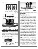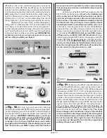
page 13
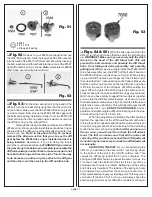
#6 22 2
4 -40/5 -4 0
n ylon lo ckn u t
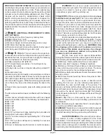
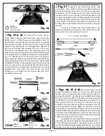
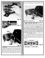
Fig. 34
❏
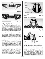
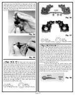
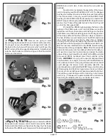
Fig. 35 & 36
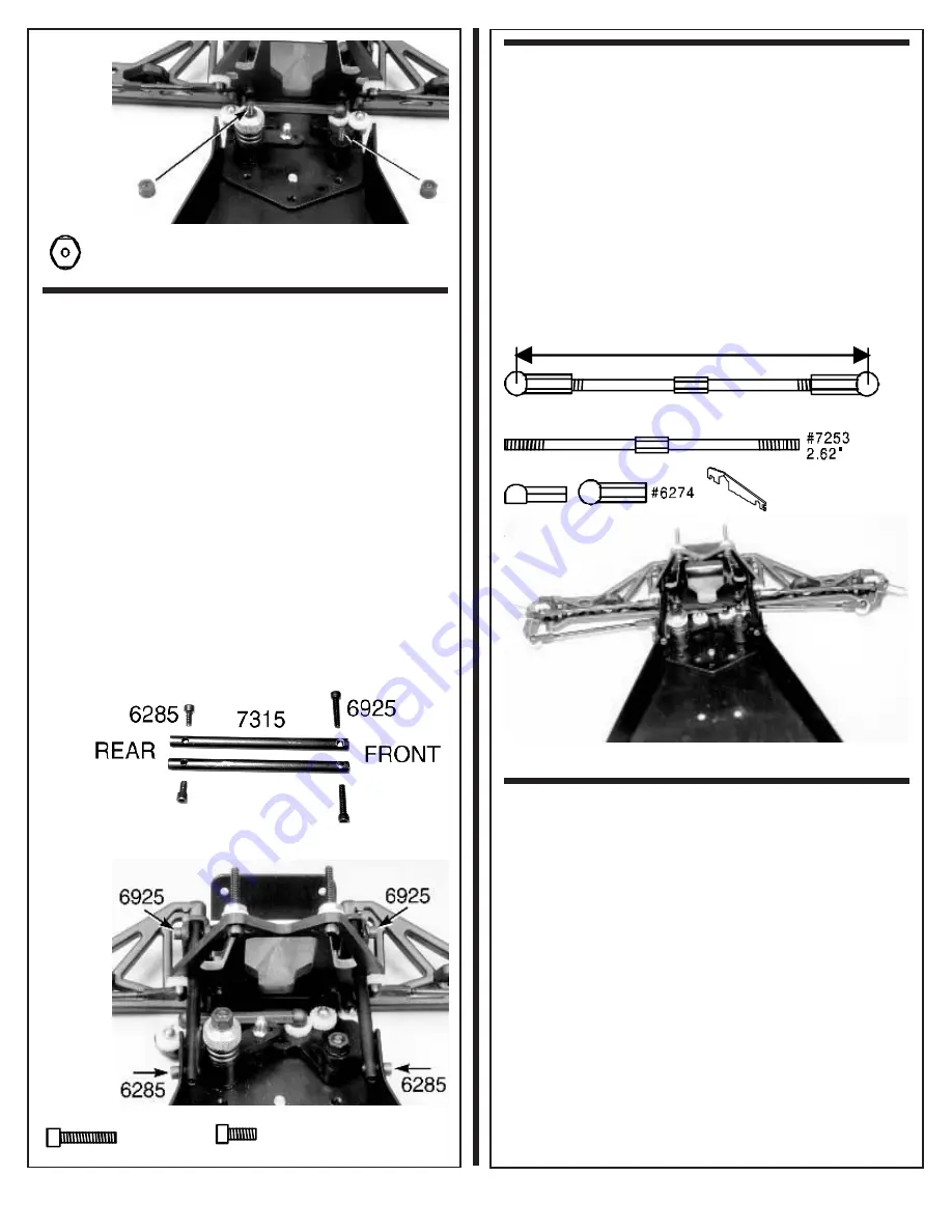
From bag #7-4 remove the two
#7315 black anodized nose brace tubes. Also remove two
#6925 4-40 x 1/2" SHCScrews and two #6285 4-40 x 1/4"
SHCScrews. Look closely at a nose brace tube. You will see
that one tube end has one hole closer to the end of the tube
than the other and that it is an unthreaded hole. Slip the end
with the unthreaded hole towards the front of the truck,
through the oval shaped hole on the passenger side of the
black front shock strut. Align the hole in the tube with the hole
in the saddle of the front bulkhead. Install one of the #6925 4-
40 x 1/2" SHCScrews in the front hole but do not tighten it
down all the way. Now line up the back hole in the nose brace
tube with the back hole on the front side of the chassis install
the #6285 SHCScrew. Now go back and do the same for the
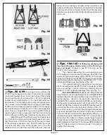
other nose brace tube. Fig. 36 shows the front of the chassis
showing the four mounting hole locations with the screws
installed. After both tubes and their screws have been
installed you can tighten all four screws. Be sure not to
overtighten the screws.
Fig. 35
# 69 25
4 -4 0 x 1 /2
#62 85
4-40 x 1 /4
ste el
Fig. 36
❏
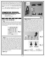
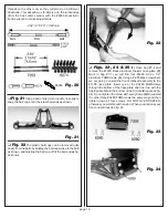
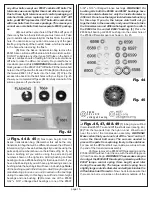
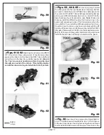
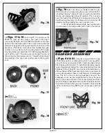
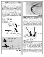
Fig. 37
In bag #7-2 you will find two #7253 2.62"
turnbuckles. From bag #6-14 remove four #6274 ball cups.
Thread the ball cups onto each end of the two turnbuckles.
Remember the turnbuckles have both right and left hand
threads, and on one end of each turnbuckle the ball cup will
thread on the opposite way. The drawings with this step show
the actual assembled dimension with the ball cups and the
actual length of the #7253 turnbuckle. On these two turn-
buckles (when assembled) the ball cups all face the same
direction.
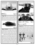
Using your needle nose pliers install both of the
steering turnbuckles onto the servo saver ball ends and the
steering arm ball ends as shown in fig. 39.
3.17" (3 11/64", 80.55mm)
#6274
#7253
#6274
#6955
Fig. 37
❏
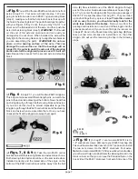
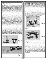
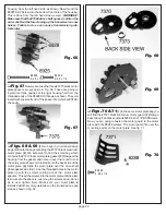
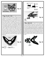
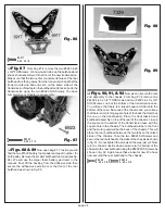
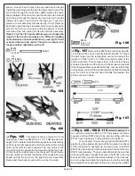
Figs. 38, 39 & 40
(1) Locate bag #7-5 and
remove the black nylon body mount tree. Fig. 38 shows the
location of the front and rear body mounts on this parts tree.
Remove the two #7319 front body mounts. (2)Go back to bag
#7-5 and remove the #7318 front body mount brace and the
two #6918 4-40 x 1/2" BHSScrews. (3) Use your #6950 1/16"
Allen wrench from the Tool bag to mount the front body
mounts to the front body mount brace, as shown in fig. 39,
with the two #6918 screws.
Note: To hold the front body
mount while you are tightening the screw you can use one of
the #6332 body clips (hood pins) installed in its mounting hole
to hold the mount. (4) Align the small body clip holes in the
ends of the body mounts so they point to the left and right. (5)
Tighten the screws but not too tight.
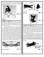
(6)Now we need to install the front body mount brace
assembly onto the front bulkhead. Take two #6924 4-40 x 3/
8" SHCScrews from bag #7-5. Install the body mount brace
over the front bulkhead, facing towards the back. This will put
the body mounts over the bulkhead as well and they will be


