page 20
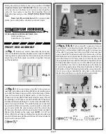
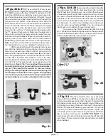
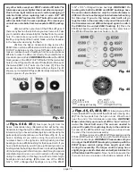
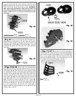
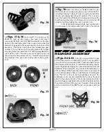
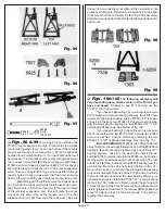
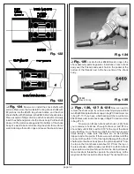
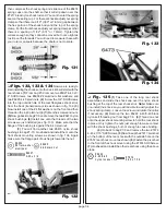
Fig. 68
Fig. 69
❏
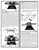
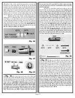
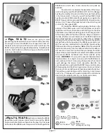
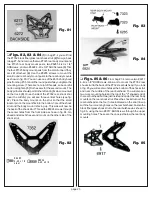
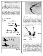
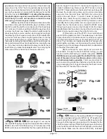
Figs. 70 & 71
(1) In the same motor plate bag you
will find the #7371 black aluminum motor guard. (2) Now go
back to bag F and take out two #6288 4-40 x 1/4" BHSScrews.
Now you are going to fasten the motor guard to the motor
plate with the #6288 screws. The motor guard fits over the
mounting points on the motor plate. See fig. 71.
Fig. 70
# 62 88
4 -40 x 1/4
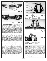
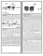
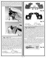
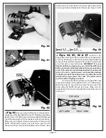
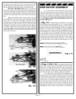
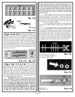
housing, from the left hand side, as shown. Now thread the
#6925 SHCScrew into the bottom front hole of the housing.
This is done from the left hand side as well.
WARNING!:
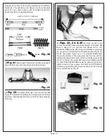
Make sure that the #7669 drive shaft spacer is still on the
outer shaft end before closing up the transmission case
halves. Failure to do so can cause transmission prob-
lems later.
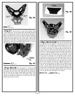
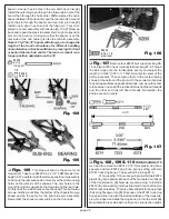
Fig. 66
# 6928
4 -4 0 x 1
#69 25
4-40 x 1 /2
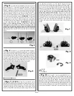
❏
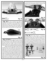
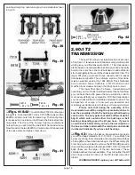
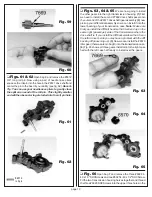
Fig. 67
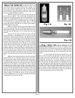
Now we can take the three #7375 black motor
plate spacers we set aside in Fig. 56. These are going to
install into three cavities of the right housing half over the
threaded ends of the #6928 SHCSrews as shown. They will
install with the small end of the spacer first which will fit into
the cavity.
Fig. 67
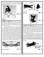
❏
Figs. 68 & 69
(1) Go back to your transmission
bag and locate the bag containing the #7370 black aluminum
motor plate. (2) We also want to find the small bag which
contains the #7373 foam motor plate gasket. (3) Now peal the
backing from the gasket and center it over the round hole in
the motor plate. We want to install it onto the back side of the
motor plate. (4) Slide the motor plate over the drive shaft
(foam gasket side first). Line the threaded holes in the motor
plate up with the screws coming out of the motor plate
spacers. Thread the screws into the motor plate until the plate
is secured to the spacers. Just snug the screws down, do not
try to over tighten them. Make sure your motor plate is
installed with the motor guard tabs on the transmission case
side as shown in fig. 69

