page 41
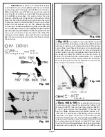
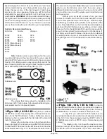
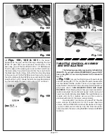
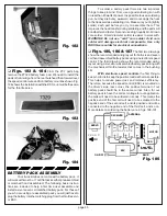
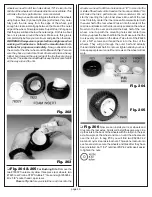
Fig. 162
❏
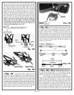
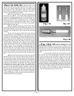
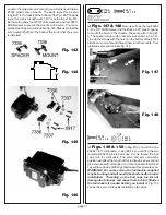
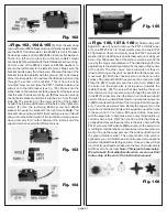
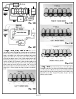
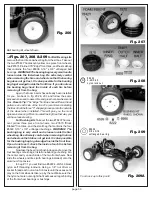
Figs. 163, 164 & 165
(1) From the same bag
remove the two #8850 black aluminum throttle resistor brack-
ets, the #6711 throttle resistor, two #6932 4-40 x 5/16" socket
head cap screws, and two #6936 #4 aluminum flat washers.
There is a left and a right side to the two resistor mount
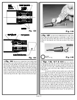
brackets.(2)We will start with the left bracket as shown in fig.
163. Use one of the #6932 screws and #6936 washers to
secure the left bracket to the left side mount. Make sure the
bracket bends away from the servo. We want the top of the
bracket to also be parallel with the ground. (3) Look closely
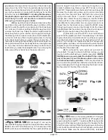
at the throttle resistor. You will see that there is a slot running
through the center of the resistor. This is how it will be
mounted. Now we can take the #6711 throttle resistor and
slide it onto the left bracket (see fig. 165). Make sure the
solder tabs on the resistor are facing away from the servo and
that the silver bands are facing up. (5) Next we can pick up
the right side bracket and slide it into the slot from the right
side. (6) The small slot on the lower portion of the bracket
needs to be lined up with the mounting hole on the right servo
mount. (7) Use the remaining #6932 screw and #6936
washer to secure the bracket to the right mount.
Note: The
brackets have vertical slots for the mounting screws. This will
allow us to adjust the height of the resistor to make sure we
have good electricl contact between the resistor and the
wiper arm when used with different servos.
Fig. 163
Fig. 164
Fig. 165
❏
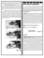
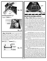
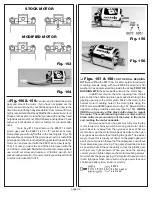
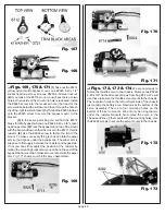
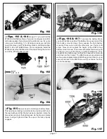
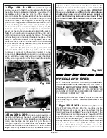
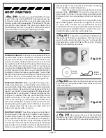
Figs. 166, 167 & 168
(1) Still working with
bag #6-13 we will need to remove the #6712 throttle wiper
arm, one #3721 #2 x 1/4" sheet metal screw, and one #3721
#2 flat washer (there is normally an extra #3721 screw and
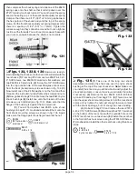
washer).(2)Look at the servo horns that came on or with your
servo. Fig. 166 shows five of the more common servo horns
used by the major manufacturers. The ideal design (for this
application) is the small round servo horn shown in the center
of the photo. The other servo horns will work but they do
require trimming so they will not interfere with the wiper arm
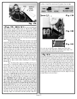
movement. (3) Push the chosen servo horn back onto the
spines of the output shaft of the servo but do not secure it. (4)
Place the #6712 wiper arm over the servo horn. Make sure
the button on the wiper arm is facing down (towards the
resistor bands). (5) The screw that was holding the servo
horn that came on your servo will go through the center slot
in the #6712 wiper arm, then the servo horn and secure both
parts to the servo. Install this screw for now but do not secure
it.(6) Now look at the bottom of the round portion of the wiper
arm. You will see a small hole. Rotate the wiper arm on the
servo horn until the small hole will line up with one of the holes
in the servo horn. You have a little up and down movement
with the wiper arm to help make sure every thing will line up
correctly with a hole. (7) When you find a hole that lines up,
go ahead and secure the wiper arm to the servo horn with the
#3721 screw and #2 washer. (8) Now remove the servo horn
mounting screw then the servo horn/wiper arm assembly. we
want to line up the wiper arm over the wide neutral band on
the green throttle resistor. The output shaft of the servo is
splined so you can rotate the servo horn assembly one spline
at a time to adjust the starting position. Once you have it lined
up correctly go ahead and resecure the servo horn assembly
with the servo horn screw.
Note: This is just a basic setup.
We will make final adjustments when we do our final
radio setup at the end of the instruction manual.
Fig. 166

