page 42
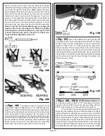
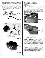
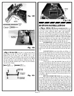
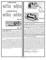
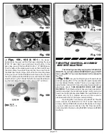
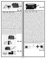
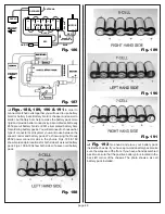
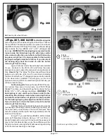
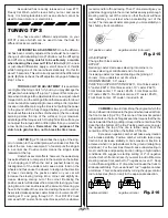
Fig. 167
Fig. 168
❏
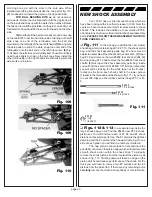
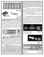
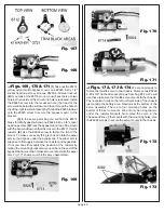
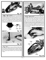
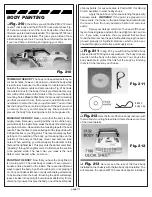
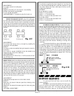
Figs. 169, 170 & 171
(1) Take out the #6714
yellow nylon throttle bypass mount, one #6925 4-40 x 1/2"
socket head cap screw, and one #6295 4-40 steel locknut.
(2) If you look at the #6714 mount you will see there are two
holes. On one side of the mount one hole is recessed. Install
the #6925 screw into the recessed hole (the head of the
screw will be below the surface) and then through the hole on
top of the right resistor bracket. (3) Thread the #6295 locknut
onto the #6925 screw to secure the bypass mount to the
bracket.
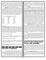
(4) In the same parts bag you will find the #6714
brass throttle bypass tab and one #6924 4-40 x 3/8" socket
head cap screw. (5) Place the bypass tab on top of the mount
with the bent end down so that it is closer to the #6711 throttle
resistor. (6) Use the #6924 screw to fasten the tab to the
mount. To make sure every thing is correct rotate the wiper
arm so that it goes under the bypass tab. The wiper arm is
suppose to fit snuggly between the resistor and bypass tab.
If not you can either adjust the position of the resistor by
raising the mounting brackets or you can bend the end of the
bypass tab down so that it makes more contact with the wiper
arm. Fig. 171 shows your throttle servo assembled.
Fig. 169
Fig. 170
Fig. 171
❏
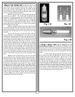
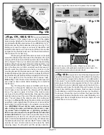
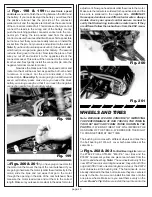
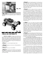
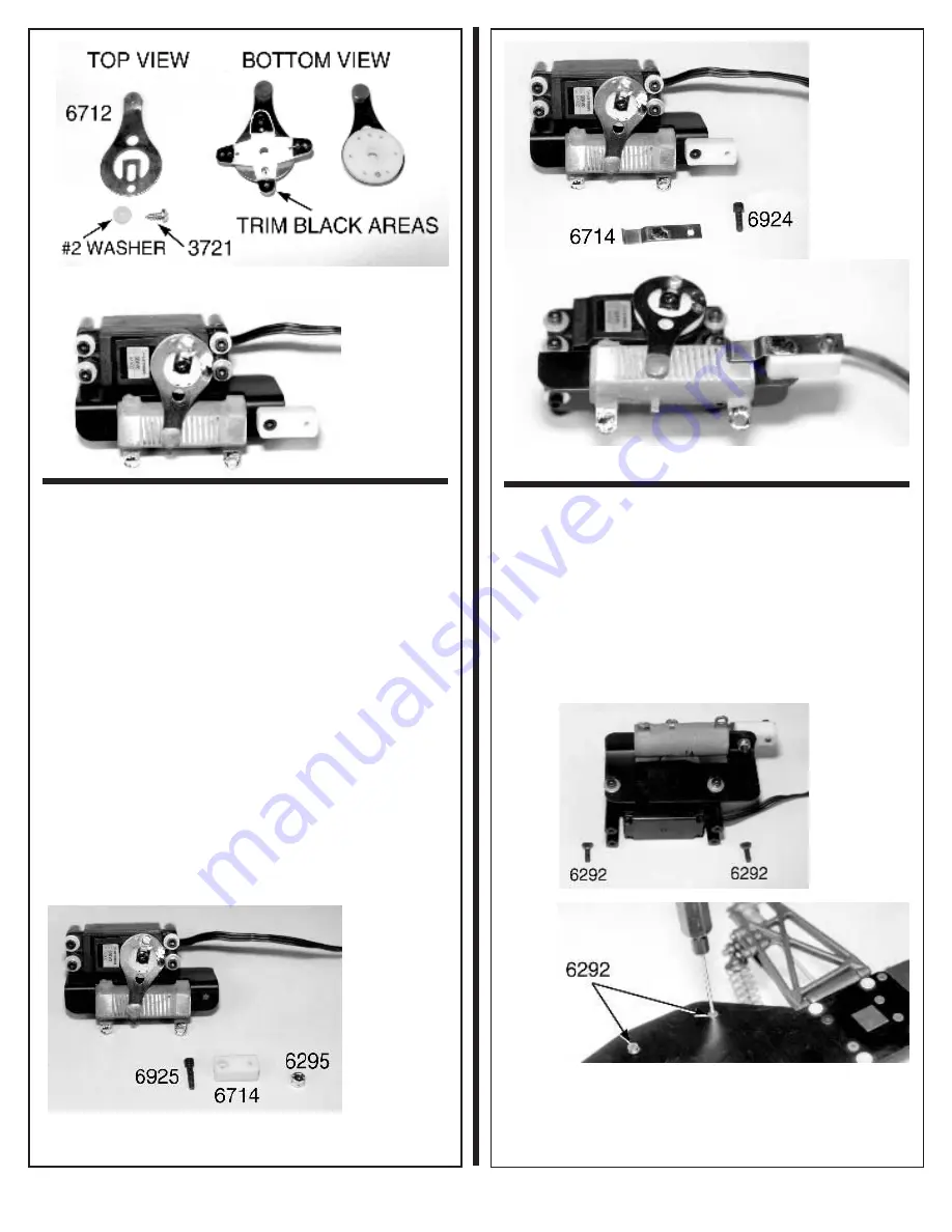
Figs. 172, 173 & 174
We are now ready to
fasten the throttle servo to the chassis. Remove two #6292
4-40 x 3/8" flat head socket screws from bag #6-13. We will
use these to secure the throttle servo mounts to the chassis.
There are two holes on the left or drivers side of the chassis
just outside the battery area. Now look at the bottom of the
servo assembly. There are four mounting holes on the
bottom of the servo mounts. We will only be using the two
under the resistor brackets. Now place the servo in the
chassis and line up the mounts with the mounting holes. Use
the #6292 screws to secure the servo mounts to the chassis.
Fig. 172
Fig. 173

