page 43
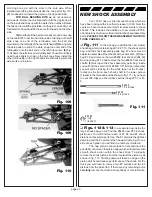
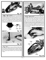
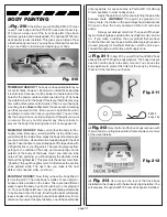
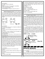
Fig. 174
❏
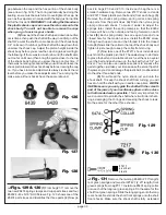
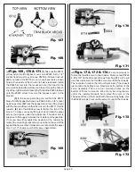
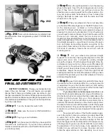
Fig. 175, 176 & 177
Now we can begin to
connect the wire harness for the throttle resistor and battery
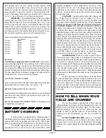
pack. (1) In bag #6-13 you will find a small 2 inch piece of red
16 guage wire. (2) Solder one end of this wire to the #6714
brass bypass tab. Then solder the other end to the closest tab
on the #6711 throttle resistor. This will be the positive
terminal on the resistor. You can shorten the wire to improve
the efficiency and appearance of the connection. See fig.
175.
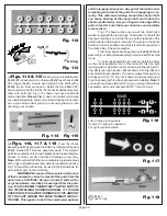
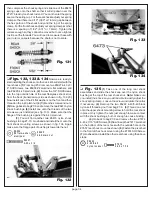
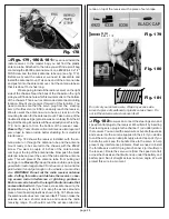
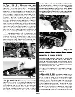
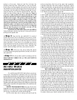
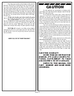
(3) Next remove the #6747 battery input power
harness (with B.E.C. plug). Solder the large red wire to the
positive tab on the throttle resistor. Now solder the large black
wire to the negative tab on the same throttle resistor Fig. 176
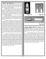
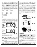
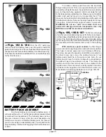
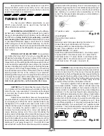
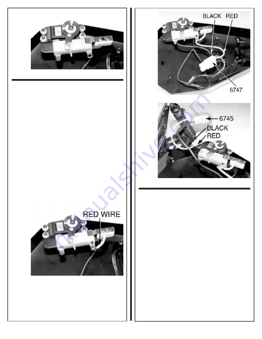
shows this harness installed on the throttle resistor. (4) The
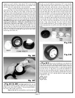
last harness we need is the #6745 motor output plug. For this
plug we will solder the red wire to the #6712 brass wiper arm
on the servo. We will then solder the black wire to the
negative tab on the left side of the throttle resistor. Fig. 177
shows this harness plug installed. Now connect the #6745
motor output plug to the motor plug that is soldered onto the
motor. Your mechanical throttle control is now assembled
and installed. We will check the setup and make any
adjustments in the final adjustments section later in the
manual.
Fig. 175
Fig. 176
Fig. 177
❏
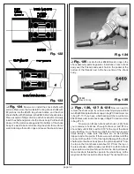
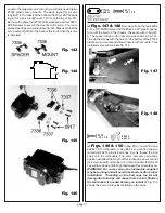
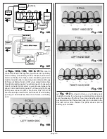
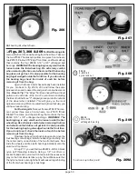
Fig. 178
FOR BALL BEARING KITS we are now
going to install the electronic speed control. If you have not
decided on a speed control yet, we recommend using a name
brand like LRP, Novak, or Tekin. We consider this to be the
top brands from Europe and the U.S. As long as you stay with
a quality brand you should have no problems.
NOTE: Bush-
ing kit owners will need to follow this step if you ever
decide to upgrade to an electronic speed control.
In your kit bag you will find a two strips of double stick
servo tape. trim a piece to fit the bottom of the ESC (electronic
speed control) case. Peel the backing from one side and
secure the tape to the case. You want to mount the ESC in
the back left corner of the chassis as shown in the photo. Try
to mount the ESC so that air can flow through the FET's or
heat sinks, if possible. Now cut a small piece of double stick
tape to fit the on/off switch on the ESC and use it to secure
the switch in the position you want.

