page 45
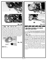
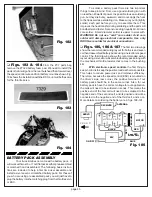
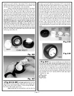
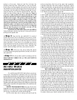
Fig. 182
❏
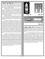
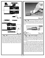
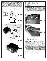
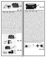
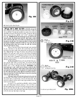
Figs. 183 & 184
From the #7-7 parts bag
remove the #7329 battery foam pad. We need to install the
pad so that it will go from the rear bulkhead then forward over
the speed control wire and front battery mount as shown. Fig.
184 shows the installation with the ESC, but it will be the same
for the throttle servo.
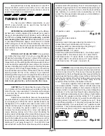
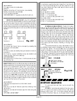
Fig. 183
Fig. 184
c
o
n
n
e
c
t
t
i
o
n
BATTERY PACK ASSEMBLY
Your truck kit does not come with a battery pack. It
will work with most 6 or 7 cell flat packs either pre assembled
or matched hand assembled. The following basic instruc-
tions are included to help a first time user assemble and
install a six or seven cell matched battery pack. For those of
you who are using pre assembled pack you will just have to
plug the battery into the matching plug from the throttle servo
or ESC.
To solder a battery pack there are two important
things to keep in mind. First, use a good soldering iron with
no less than 40 watts of power. It is possible to use a soldering
gun, but they are bulky, awkward, and do not apply the heat
to the tip as well as a soldering iron. Make sure you tin (lightly
solder) each part before you try to assemble them. This
improves the heat transfer during soldering and the parts will
bond better and faster. Second, use a high quality 60-40 rosin
core solder. Small diameter solder is easier to work with.
WARNING! Do not use "acid" core solder. Acid core
solder will damage electrical components. Use only
ROSIN core solder for electrical connections.
❏
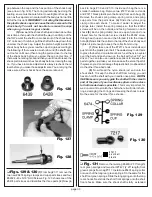
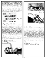
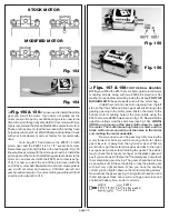
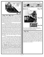
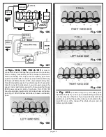
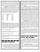
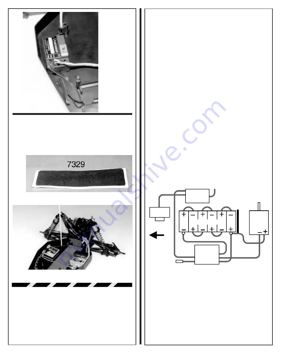
Figs. 185, 186 & 187
The first two drawings
show the recommended wiring layout for both six and seven
cell hand assembled battery packs using an electronic speed
control. The third drawing shows the recommended wiring
layout using a six cell pre-assembled battery pack along with
the mechanical throttle resistor that comes in the bushing
kits.
With electronic speed controls the first thing to
keep in mind is to keep the positive lead as short as possible.
This helps to reduce power loss and improves efficiency.
Therefore, because the speed control (ESC) is mounted on
the driver's side rear corner, the positive terminal of our
battery pack should be in the same corner. Also, for our
battery pack to have the correct voltage for our application,
the cells will need to be soldered in series. This means the
positive end of the first cell will need to be soldered to the
negative end of the second cell, and its positive end will be
connected to the negative end of the third cell, and so on.
More details on soldering the battery are in figs. 188-191.
RECEIVER
SERVO
ESC
MOTOR
ON/OFF
ANTENNA
BLACK
BLUE
RED
RED
BUL
KHEAD
FR O N T
keep RED
wires short
6-C E LL P A C K
Fig. 185

