10
/
13
4. Product Function and Usage
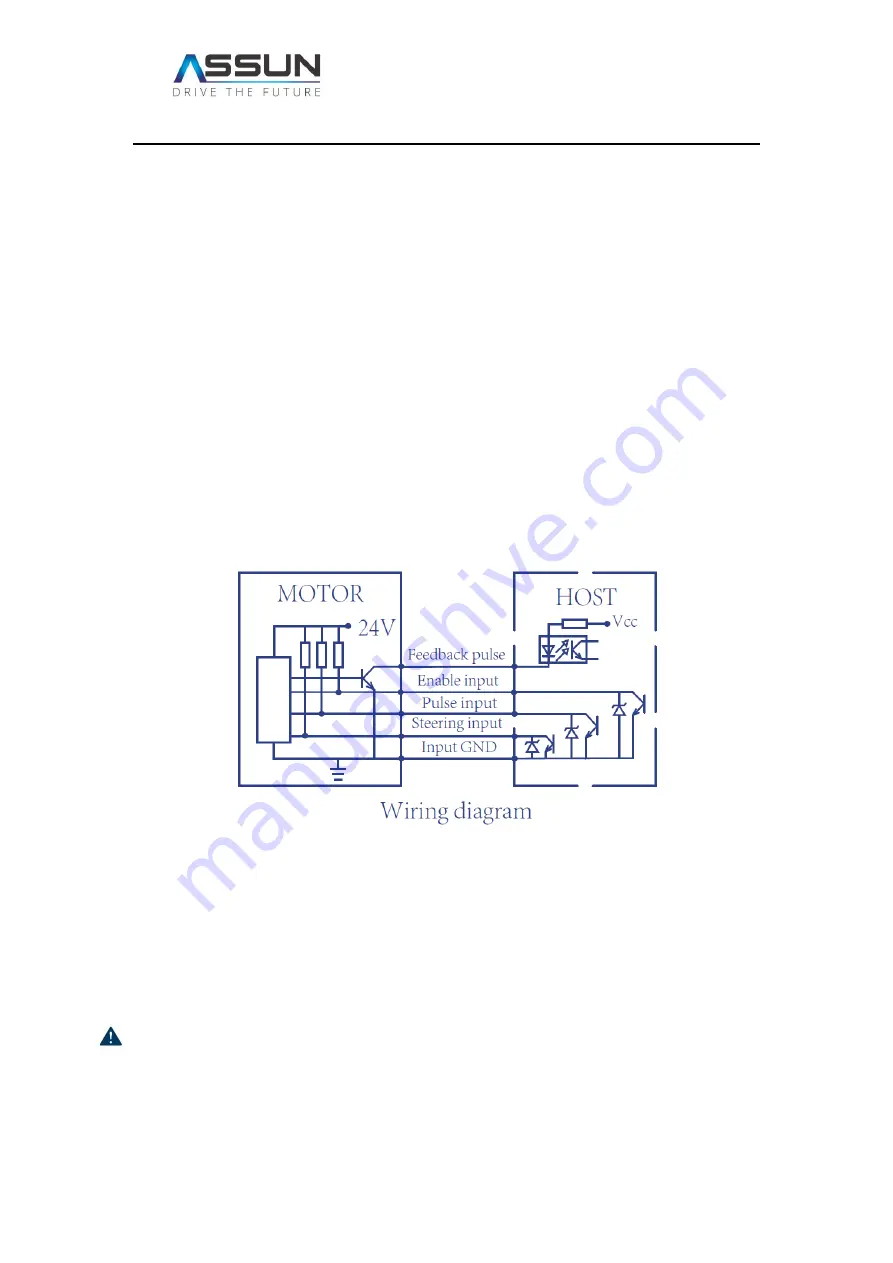
The Product Series has five control cables and two power supply cables.
Two power cables are red cable (connect to power supply positive) and blue cable (connect
to power supply negative).
Five control cables include ground cable (black), rotating direction control (white), feedback
pulse (green), pulse input cable (white) and enable input (yellow). These cables are enclosed
in a black shielding cable for better stability. Analogue voltage input is defined as low voltage
input to be 0-1.2V and high voltage input to be 22-24V.
The enable input must be supplied with low voltage or connected to GDN for the motor to
operate. Motor rotating speed controlled by pulse input. Commonly the control wiring
diagram are proposed as following:
4.1 Motor Installation and Power Connection
Motor must be properly and securely mounted., typically utilizing the treaded holes in the
front cover to fix the motor. It will be proposed to install the motor to metal parts, or installed
in well ventilated environments for better heat dissipation.
There are two AWG20# power cables, one is red cable that should be connected to the
positive of power supply, the other is blue cable which should be connected to the negative
of power supply. The power connection must obey the indication above. If the power supply
is inadvertently reversed, it will seriously damage the internal driver causing malfunction of
the motor.


