5
media at the operational pressure for the unit (typically in the range of 5-15 PSI).
The shutoff pressure
off the pump should be less than 20 psi, or near 20 psi when a pressure relief is installed to avoid
damaging the HPPG hull.
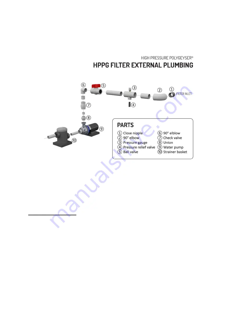
HPPG Filter External Plumbing illustrates a typical plumbing arrangement. In most case the pump (9)
should be protected by a screen or an inline screen basket (10). Many pumps already have the inline
basket attached. A hard PVC couple (8) is placed immediately adjacent to the pump discharge to
facilitate pump replacement or servicing. A rubber or flexible couple should be avoided here, as they
are sensitive to pump vibration tend to work loose.
This coupling is followed immediately by a
mandatory check valve (7) which prevents the backflow of beads into the pump during periods of
power interruption.
If the pump’s flow capacity is significantly greater than the filters rating then a ball
valve (5) is then placed in line to allow the pump to be throttled to manage flow through the HPPG unit.
Alternately a “tee” can be placed at this location with two ball valves allowing for flow to bypass the unit
to a parallel use. You will find a 0-30 psi pressure gauge (3) will greatly facilitate the management of
the filter. High pressures are an indication to increase the backwash frequency.
Finally, in situations
where either the water pump or the backwashing air pump have high shutoff pressures (>20 psi) then
a pressure relief valve must be placed immediately adjacent to the filter input to assure protection of
the hull.
The pressure relief valve can be set to pop at 20 psi. All HPPG filters are pressure tested at a
higher pressure to ensure quality prior to shipping, but the operational pressures should not exceed 20
psi.


