6
Airlift Configuration
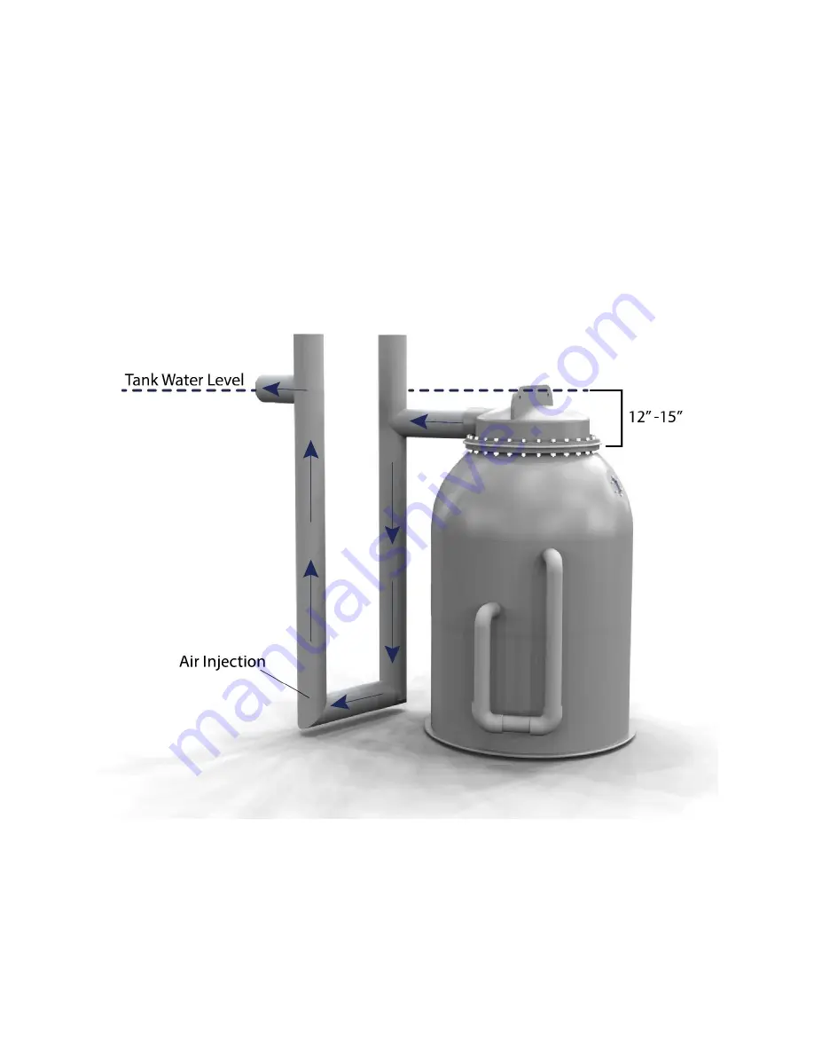
The HPPG series is equipped with an oversized screen and inlet/outlet plumbing to facilitate airlift
operation. Typically, the filter must be positioned next to the tank so that the screen is 12-15” below
the water level in the tank. The siphoning outlet pipes are then directed toward the ground to develop
pressure for the airlift operation. The discharge pipes are then curve back to the vertical draft tube. Air
is injected near the bottom of the draft tube to create a low density air/water mixture that is pushed
upward by the dense water in the siphon line. The elevated air and water mixture is then moved
horizontally to the tank.
Water Flow in an Airlifted HPPG: Water exits from the top of the filter, into the U pipe. Air injected into
the far draft tube pushes the water up and out of the pipe, back into the tank.


