C
H A P T E R
4
D
I S P L A Y I N G
M
A C H I N E
D
A T A
1 2 2
6 7 1 0 D G
R I N D E R
O
P E R A T O R
S
A F E T Y
M
A N U A L
1 0 9 4 0 1 B
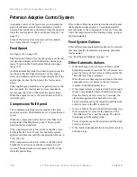
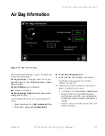
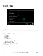
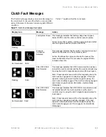
Feed System
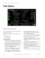
Figure 114:
Feed System Information Page
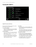
The Feed System page (Figure 114) shows the current
status of the feed system.
The display page is divided into the following two sec-
tions:
•
Compression Roll
•
Feed Conveyor
Compression Roll
•
The direction arrows indicate directions (forward,
reverse, up, down) the compression roll is moving.
•
The compression roll bar graph and the numerical
readout below the bar graph on the left side indicate
the height of the compression roll in inches.
The compression roll does not press down automat-
ically below the
Min Down
point.
The compression roll applies down pressure when it
gets pushed above the
Max Auto Lift
point.
If the compression roll continues to get pushed
above the
Max Push
point, the feed chain reverses.
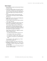
•
Compression Roll Auto Lift
displays the
selected status for the auto lift function: lifts On
Reverse, On Stop, or Disabled
To change this setting, touch the displayed status.
•
The speed of the compression roll is displayed as
RPM and seconds per revolution.
•
Compression Roll Up/Down displays the current
output to the compression roll lift valve, shown in
milliamperes.
•
Pressure indicates the hydraulic pressure in psi
required to turn the compression roll.
•
The maintenance icon provides navigation to the
compression roll setup page (page 145).
•
Compression Roll Ratio
indicates the ratio of
the compression roll speed (ft/min) to the feed chain
speed (ft/min).
To change this ratio, press the displayed percentage.
F11240
Summary of Contents for Peterson 6710D
Page 6: ...C O N T E N T S 4 67 1 0 D G R I N D E R O P E R A T O R SA F E T Y M A N U A L 109401B ...
Page 158: ...16 2 67 1 0 D G R I N D E R O P E R A T O R SA F E T Y M A N U A L 109401B ...
Page 166: ...I N D E X 17 0 67 1 0 D G R I N D E R O P E R A T O R SA F E T Y M A N U A L 109401B ...
Page 167: ......

