C
H A P T E R
5
T
R A N S P O R T I N G
T H E
6 7 1 0 D
1 5 2
6 7 1 0 D G
R I N D E R
O
P E R A T O R
S
A F E T Y
M
A N U A L
1 0 9 4 0 1 B
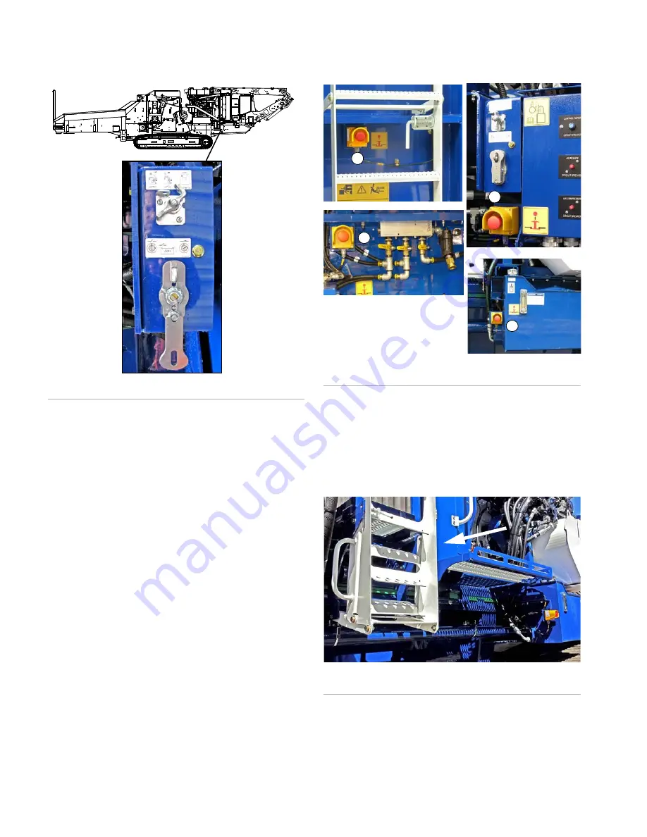
Figure 131:
Electrical Disconnect Switches, Location
7.
Make sure all emergency stop buttons are pulled
out. There are five E-stops on the machine:
•
one E-stop on the control panel (Figure 134)
•
four E-stops on the machine frame (Figure 132)
Figure 132:
Emergency Stop Buttons, Locations
8.
Unlock and open the vandal guard for the control
panel.
9.
Fold up the ladder (Figure 133) to the service deck
in its upright position and install the spring-loaded
latch.
Figure 133:
Service Deck/Engine Access Ladder
F08287
F08089
F10040
F08027
F08803
F08798
1. Behind hopper ladder
2. Below disconnect switches
3. Near water sprinkler valves
4. Next to clutch oil tank
1
2
3
4
F09470
Summary of Contents for Peterson 6710D
Page 6: ...C O N T E N T S 4 67 1 0 D G R I N D E R O P E R A T O R SA F E T Y M A N U A L 109401B ...
Page 158: ...16 2 67 1 0 D G R I N D E R O P E R A T O R SA F E T Y M A N U A L 109401B ...
Page 166: ...I N D E X 17 0 67 1 0 D G R I N D E R O P E R A T O R SA F E T Y M A N U A L 109401B ...
Page 167: ......


