C
H A P T E R
3
O
P E R A T I N G
T H E
6 7 1 0 D
1 0 9 4 0 1 B
6 7 1 0 D G
R I N D E R
O
P E R A T O R
S
A F E T Y
M
A N U A L
7 9
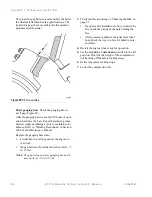
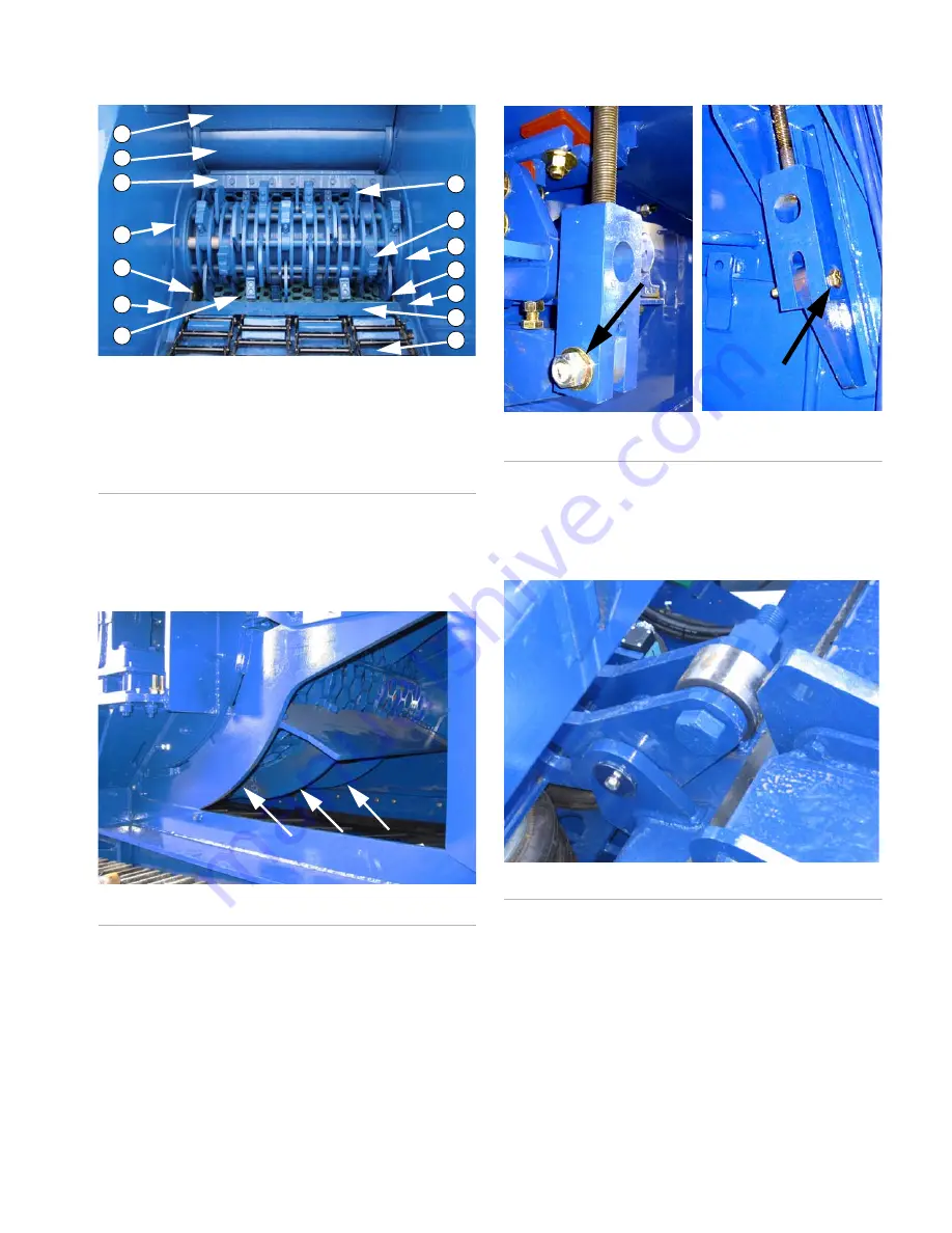
Figure 81:
Grinder Assembly
Grate supports
(Figure 82), also called banana
bars. Check for bent and damaged items. Make sure
they are not loose or dragging on the discharge belt.
Figure 82:
Grate Access and Grate Supports
Grate support shear bolts
(Figure 83). Make sure
they are not over-tightened. Properly tightened
bolts can be turned easily with a wrench.
Figure 83:
Grate Support Shear Bolts
Impact release system latch and roller
(Figure 84). Check for compacted material that pre-
vents operation of the latch.
Figure 84:
IRS Latch and Roller
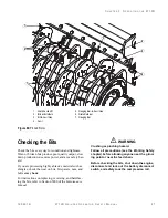
Bit-to-anvil gap
. Make sure the gap between the
anvil and bits is 3/8 to 3/4 in. (10-20 mm)
(Figure 85 and Figure 86 on page 81).
The anvil can be turned over one time to expose a
new wear surface.
F05533
1. Compression Roll Housing
Wear Plate
2. Anvil Housing Wear Plate
3. Anvil
4. Rotor Wear Plates
5. Grate #4
6. Gauging Bar
7. Bit Holder and Bit
8. Feed Plate (T-bar)
9. Head Deck Plate
1
2
3
4
4
4
4
4
4
5
6
7
8
9
F05424
F08353
F08354
F05613
Summary of Contents for Peterson 6710D
Page 6: ...C O N T E N T S 4 67 1 0 D G R I N D E R O P E R A T O R SA F E T Y M A N U A L 109401B ...
Page 158: ...16 2 67 1 0 D G R I N D E R O P E R A T O R SA F E T Y M A N U A L 109401B ...
Page 166: ...I N D E X 17 0 67 1 0 D G R I N D E R O P E R A T O R SA F E T Y M A N U A L 109401B ...
Page 167: ......


