C
H A P T E R
3
O
P E R A T I N G
T H E
6 7 1 0 D
8 0
6 7 1 0 D G
R I N D E R
O
P E R A T O R
S
A F E T Y
M
A N U A L
1 0 9 4 0 1 B
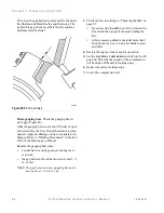
The closer the gap between anvil and bits, the better
the final material matches the specifications. The
tighter this gap, the more efficiently the machine
produces sized material.
Figure 85:
Bit-To-Anvil Gap
Rotor gauging bars
. Check the gauging bar-to-
anvil gap (Figure 86).
After the gauging bars wear about 50 hours of oper-
ation, hard face the bars. Repeat hard-facing when
needed. Apply hardfacing evenly to maintain rotor
balance. Refer to “Welding Precautions” in Section
3000 of the
Maintenance Manual
.
Replace the gauging bars when:
•
a wider bar-to-anvil gap causes the engine to
overwork
•
the gap between the old bar and a new anvil = 2
in. (5 cm)
N
OTE
:
The gap between a new gauging bar and a
new anvil is 1-1/8 in. (3 cm).
3.
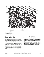
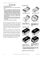
Check the bits according to “Checking the Bits” on
page 81.
•
If you recently installed new bits or rotated the
bits, check the torque of the nuts holding the
bits.
•
After processing abrasive material more than 1
hour, check the wear on bits, bit holders, nuts,
and bolts.
4.
Restart the engine when ready for operation.
5.
Set the
MATERIAL
COMPRESSION
switch to the lift
position. This lifts the weight of the compression
roll housing off the safety locking stops.
6.
Retract the safety locking stops.
7.
Lower the compression roll.
F03597
Summary of Contents for Peterson 6710D
Page 6: ...C O N T E N T S 4 67 1 0 D G R I N D E R O P E R A T O R SA F E T Y M A N U A L 109401B ...
Page 158: ...16 2 67 1 0 D G R I N D E R O P E R A T O R SA F E T Y M A N U A L 109401B ...
Page 166: ...I N D E X 17 0 67 1 0 D G R I N D E R O P E R A T O R SA F E T Y M A N U A L 109401B ...
Page 167: ......


